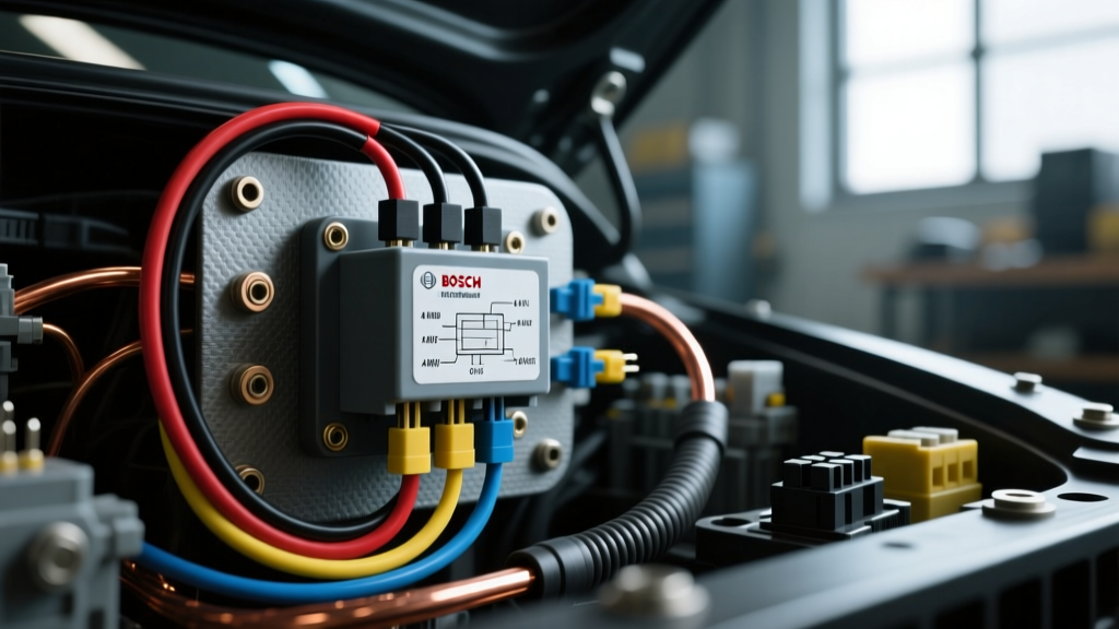
Introduction to the ISO/Bosch 4-Pin Relay in Towing Applications
When modifying or upgrading trailer electrical systems, the 4 pin relay wiring diagram represents the foundational building block for high-current circuit isolation. Modern tow vehicles utilize multiplexed wiring networks and Body Control Modules (BCMs) that are highly sensitive to overcurrent conditions. Factory trailer lighting circuits are typically limited to 5 to 10 amps per channel. If you are adding auxiliary LED trailer lights, electric winch solenoids, or heavy-duty reverse lamps, drawing current directly from the vehicle's OEM 4-way flat connector will trigger a BCM fault code or blow a surface-mount fuse. By implementing a standard ISO/Bosch-style Single Pole Single Throw (SPST) relay, you use the low-current OEM signal solely to trigger the relay coil, while the heavy current required by the trailer accessory is sourced directly from the vehicle battery or a dedicated high-amperage auxiliary bus.
Standard 4-Pin Relay Pinout Specifications (DIN 72552)
Automotive relays adhere to the DIN 72552 standard for terminal numbering. Understanding these designations is critical when interpreting any 4 pin relay wiring diagram, as misidentifying the coil terminals from the contact terminals will result in an immediate short circuit or a damaged control module.
| Terminal (Pin) | Function | Circuit Type | Standard Wire Color |
|---|---|---|---|
| 85 | Coil Ground | Control (Low Current) | Black / White |
| 86 | Coil Power (+12V) | Control (Low Current) | Green / Blue |
| 30 | Common Input (Source) | Load (High Current) | Red (Battery +) |
| 87 | Normally Open (Output) | Load (High Current) | Yellow / White |
Note: Some relays include an internal flyback diode between pins 85 and 86 to suppress voltage spikes when the magnetic field collapses. If your relay has a diode, terminal 86 MUST be connected to the positive (+) trigger source, and terminal 85 MUST be connected to ground. Reversing polarity on a diode-protected relay will prevent the coil from energizing.
Wire Gauge (AWG) and Current Capacity Matrix
A common failure point in trailer wiring is utilizing undersized wire for the relay load circuit. Voltage drop over the length of a 20-foot trailer harness can cause auxiliary lights to dim or winch solenoids to chatter. The following matrix dictates the minimum American Wire Gauge (AWG) required based on the relay contact rating and total circuit length (round trip).
| Max Load (Amps) | 0-10 ft Length | 10-20 ft Length | 20-30 ft Length |
|---|---|---|---|
| 10A - 15A | 16 AWG | 14 AWG | 12 AWG |
| 20A - 30A | 12 AWG | 10 AWG | 8 AWG |
| 40A (Heavy Duty) | 10 AWG | 8 AWG | 6 AWG |
The control circuit (pins 85 and 86) only draws approximately 150mA to 200mA (based on a standard 70-ohm coil resistance at 14.4V). Therefore, 18 AWG primary wire is perfectly adequate for the trigger and ground sides of the relay, minimizing bulk in the vehicle's wiring loom.
Trailer Integration: Auxiliary Reverse Light Harness
The Problem: BCM Overload on Factory Tow Packages
Many late-model trucks (e.g., 2015+ Ford F-150, Ram 1500) monitor the resistance of the trailer lighting circuits. If you plug in a trailer with additional LED reverse lights wired directly into the OEM 7-way RV blade (Pin 3 - Auxiliary or Pin 2 - Reverse), the BCM detects the abnormal current draw and shuts down the circuit to protect the multiplexed driver.
The Solution: 4 Pin Relay Wiring Diagram Implementation
To bypass this, we use the OEM reverse light signal strictly as a logic trigger. The 4 pin relay wiring diagram for this application routes as follows:
- Pin 86 (Coil Power): Splice into the vehicle's OEM 7-way reverse light pin (Center pin on a 4-way flat, or Pin 2 on a 7-way RV blade) using a Posi-Tap connector. This provides the +12V trigger when the transmission is shifted into reverse.
- Pin 85 (Coil Ground): Secure to a clean, bare-metal chassis ground using a ring terminal and a self-tapping sheet metal screw. Apply dielectric grease to prevent galvanic corrosion.
- Pin 30 (Common Source): Connect directly to the vehicle's auxiliary battery stud or a dedicated 40A fused distribution block under the hood using 10 AWG wire. Do NOT source this from the factory tow package battery charge wire, as it is often limited to 30A and shared with the trailer breakaway system.
- Pin 87 (Load Output): Run 10 AWG wire from Pin 87 to the trailer plug's auxiliary pin, which feeds the high-current LED reverse light bar on the trailer.
Advanced Connector Selection and Weatherproofing
Trailer environments are subjected to high-pressure water, road salt, and extreme vibration. Standard spade terminals will fail rapidly in these conditions. When executing your 4 pin relay wiring diagram, utilize sealed connector systems:
- Relay Socket: Use a Delphi Weather-Pack or Metri-Pack sealed relay socket with silicone plug seals. These prevent moisture wicking into the relay spades.
- Splices: Avoid T-taps. Use adhesive-lined dual-wall heat shrink butt connectors (e.g., Ancor Marine grade) for all inline splices. The internal polyamide adhesive melts and seals the wire strands, preventing capillary action from drawing water into the copper.
- Mounting: Mount the relay in the engine bay or inside a sealed IP67-rated junction box on the trailer tongue. Never mount a standard open-frame relay underneath the chassis where it will be bombarded by rocks and standing water.
Diagnostic Testing and Failure Modes
When troubleshooting a trailer circuit governed by a 4-pin relay, follow this systematic diagnostic tree using a digital multimeter (DMM):
- Control Circuit Verification: Set DMM to DC Volts. Probe Pin 86 and Pin 85 with the trigger active (e.g., vehicle in reverse). You should read 12.0V to 14.4V. If voltage is present but the relay does not click, proceed to step 2.
- Coil Resistance Test: Disconnect the relay. Set DMM to Ohms. Probe terminals 85 and 86 on the relay itself. A healthy 12V automotive relay will read between 65 and 90 ohms. An 'OL' (Open Loop) reading indicates a blown internal coil.
- Contact Continuity Test: Set DMM to Continuity. Probe terminals 30 and 87. With the relay de-energized, there should be no continuity. Apply 12V across 85 and 86 using a jumper wire from the battery; you should hear a distinct click, and the DMM should read near 0.00 ohms. High resistance across closed contacts indicates pitted or carbon-fouled internal contacts, necessitating relay replacement.
- Voltage Drop Test: With the circuit fully loaded and active, measure the voltage between the battery positive post and Pin 87. A reading greater than 0.5V indicates excessive resistance in the supply wiring, usually caused by a loose crimp or undersized AWG wire.
Authoritative References
For further engineering specifications regarding automotive relay standards and trailer wiring protocols, consult the following resources:
- SAE International Technical Standards - Reference SAE J2851 and related vehicular electrical architecture guidelines for multiplexed circuit protection.
- Littelfuse Automotive Mini-Relay Specifications - Detailed datasheets on DIN 72552 terminal configurations, coil resistance tolerances, and flyback diode integration.
- etrailer.com Wiring FAQ and Technical Guides - Practical application matrices for integrating relays with OEM 4-way and 7-way RV blade connectors.