Introduction to Ford F150 Trailer Wiring Fundamentals
Towing with a Ford F150 is a staple of American truck culture, whether you are hauling a lightweight utility trailer or a heavy-duty RV. However, connecting your trailer is only half the battle; ensuring the electrical systems communicate correctly is where many beginners struggle. When searching for a reliable ford f150 trailer plug wiring diagram, it is crucial to understand that truck-side wiring and trailer-side wiring often follow different color conventions. This guide breaks down the essential 7-pin RV blade and 4-pin flat configurations, decoding the wire colors, pinouts, and the hidden under-hood fuses that control your F150's towing capabilities.
The Factory USCAR Connector and OEM Harnesses
Modern Ford F150s equipped with the factory tow package feature a standardized USCAR (United States Council for Automotive Research) 7-way socket, typically mounted on the driver-side rear bumper. Behind this socket lies a factory pigtail harness. Crucial Beginner Warning: The wire colors on the Ford OEM harness do not always match the SAE (Society of Automotive Engineers) standard colors used on aftermarket trailers. For example, while the SAE standard for electric brakes is blue, Ford's OEM pigtail might use a light blue or even a brown wire with a tracer stripe. Always verify your specific truck's OEM pigtail with a circuit tester before splicing into an aftermarket 7-way plug.
Ford F150 Trailer Plug Wiring Diagram: 7-Pin RV Blade
The 7-pin RV blade is the industry standard for trailers with electric brakes and auxiliary power needs. Below is the standard SAE J286 pinout for the trailer side plug. When looking at the truck's socket (female side), the pin positions are mirrored. According to SAE International J286 standards, the functions and recommended wire gauges are as follows:
| Pin / Clock Position (Truck Socket) | Function | SAE Trailer Wire Color | Recommended AWG |
|---|---|---|---|
| Pin 1 (5:00) | Left Turn / Stop Lamp | Yellow | 14-16 AWG |
| Pin 2 (7:00) | Reverse Lamps / Aux | Purple | 14-16 AWG |
| Pin 3 (12:00) | Ground (Chassis) | White | 10-12 AWG |
| Pin 4 (1:00) | Right Turn / Stop Lamp | Green | 14-16 AWG |
| Pin 5 (3:00) | Electric Brake Output | Blue | 10-12 AWG |
| Pin 6 (9:00) | Tail / Running Lamps | Brown | 14-16 AWG |
| Pin 7 (11:00) | 12V Auxiliary / Battery Charge | Black (or Red) | 10 AWG |
Understanding Wire Gauge (AWG) Requirements
Notice that the Ground (Pin 3), Electric Brakes (Pin 5), and 12V Aux (Pin 7) require thicker 10-12 AWG wire. The electric brake circuit draws significant amperage (up to 12-15 amps per axle), and the 12V aux line is often used to charge a trailer breakaway battery or power interior trailer lights. Using standard 16 AWG lighting wire for these high-draw circuits will result in severe voltage drop, overheating, and potential fire hazards.
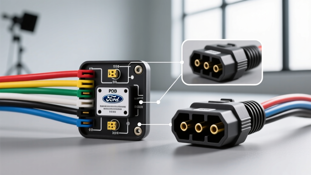
The F150 Power Distribution Box (PDB) Secret
One of the most common points of confusion for F150 owners is plugging in a trailer and finding that the 12V auxiliary pin (Pin 7) or the electric brake pin (Pin 5) has no power, even though the truck has a factory 7-way plug. According to the Ford official towing guides, many F150s require the manual installation of relays and fuses in the under-hood Power Distribution Box (PDB) to activate these specific circuits.
- 12V Auxiliary Feed: Often requires a 30A fuse (e.g., Fuse 73 or 85, depending on your exact model year) and a heavy-duty relay to be installed in the PDB. Without this, Pin 7 is completely dead.
- Trailer Battery Charge Relay: On newer 13th and 14th generation F150s, the truck's smart battery management system may only send power to Pin 7 when the engine is running and the alternator is actively charging, preventing parasitic drain when parked.
- Trailer Tow Parking Lamp: If your trailer's running lights (Pin 6) do not illuminate, check the dedicated trailer tow parking lamp fuse in the PDB. A blown fuse here will disable the brown wire circuit independently of the truck's own tail lights.
Adapting to a 4-Pin Flat Connector
If you are towing a smaller utility or boat trailer, you likely need a 4-pin flat connector. You can purchase a simple 7-pin to 4-pin adapter plug, which seamlessly steps down the connection by ignoring the electric brakes, 12V aux, and reverse circuits. For a permanent solution, you can install a 4-pin flat socket alongside your 7-way. The etrailer wiring FAQ recommends using a T-connector harness that plugs inline with the factory USCAR socket, ensuring you do not have to cut or splice into the truck's OEM wiring.
| 4-Pin Flat Pin | Function | SAE Wire Color |
|---|---|---|
| Pin 1 (Ground) | Chassis Ground | White |
| Pin 2 (Tail) | Running / Marker Lights | Brown |
| Pin 3 (Left) | Left Turn / Stop | Yellow |
| Pin 4 (Right) | Right Turn / Stop | Green |
Step-by-Step: Testing Your F150 Trailer Plug
Before connecting your trailer, verify the truck's socket using a digital multimeter (DMM) or a dedicated 7-way circuit tester.
- Set your DMM: Turn the dial to DC Volts (20V scale).
- Establish Ground: Place the black (negative) probe firmly into Pin 3 (12:00 position). If the socket is dirty, scrape the contact point lightly to ensure a solid ground connection.
- Test Running Lights: Turn on the F150's headlights. Place the red (positive) probe into Pin 6 (9:00 position). You should read between 12.2V and 14.4V.
- Test Turn Signals: Activate the left turn signal. Probe Pin 1 (5:00 position). The voltage should pulse from 0V to 12V in time with the blinker. Repeat on Pin 4 (1:00 position) for the right signal.
- Test 12V Aux: Probe Pin 7 (11:00 position). With the engine running, you should see full alternator voltage (~13.5V - 14.4V). If you read 0V, consult your owner's manual for the PDB relay and fuse locations.
Common F150 Wiring Failures and Troubleshooting
Even with a perfect wiring diagram, real-world conditions cause electrical faults. Here are the most frequent issues F150 owners face:
1. The 'Hyper-Flash' Turn Signal Issue
If your F150's turn signals blink rapidly (hyper-flash) when the trailer is connected, the truck's Body Control Module (BCM) is detecting a resistance mismatch. This usually happens when using LED trailer lights without a proper load resistor. The BCM thinks a bulb is blown and increases the flash rate to warn the driver. Install an OEM-style LED adapter module or inline load resistors to fix this.
2. Corrosion in the OEM USCAR Socket
The F150's rear bumper socket is exposed to road salt, water, and debris. Over time, the brass pins inside the female socket oxidize, causing high resistance. This manifests as dim trailer running lights or intermittent electric brake engagement. Clean the socket annually with electrical contact cleaner and apply a generous amount of dielectric grease to the pins to prevent moisture intrusion.
3. Ground Faults (The White Wire)
Over 80% of trailer lighting issues are not caused by the power wires, but by a poor ground. If your trailer's tail lights work, but the turn signals cause the entire trailer to flash erratically, the trailer's main ground wire (white) is failing to bond with the truck's chassis. Ensure the white wire is ring-terminated and bolted directly to bare, unpainted metal on the trailer tongue, and that the truck's Pin 3 is making solid contact.