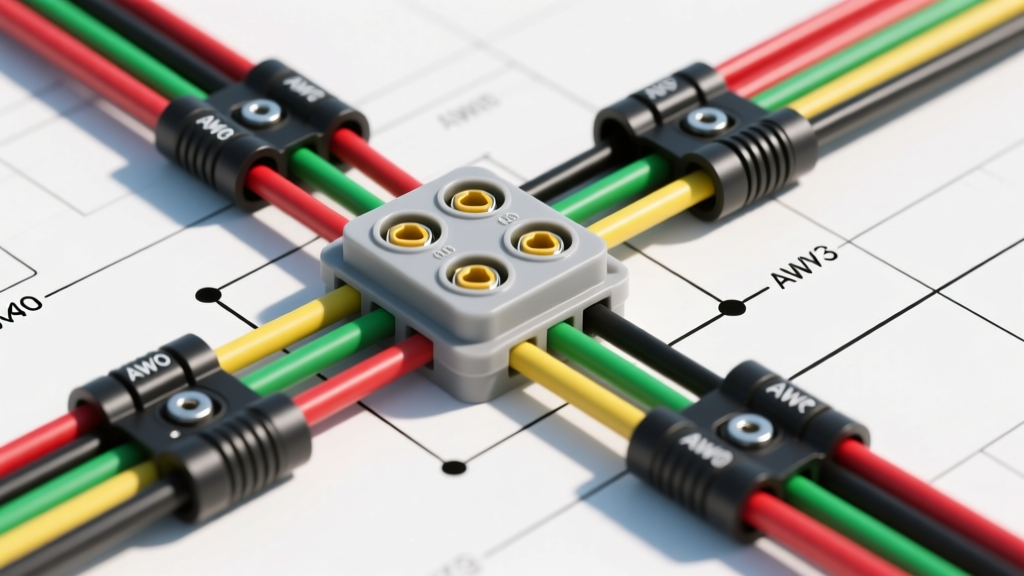
Understanding the Boat Trailer Light Wiring Diagram
Wiring a boat trailer presents a unique set of challenges that standard utility or travel trailers simply do not face. The defining factor is submersion. When you back a boat trailer into a lake or ocean, every electrical component below the waterline is subjected to rapid temperature changes, corrosive elements, and galvanic reactions. Standard automotive wiring harnesses bought at local auto parts stores will often fail within a single season when exposed to these marine conditions. To achieve a reliable, long-lasting setup, you must understand the standard boat trailer light wiring diagram and utilize marine-grade materials.
This practical how-to installation guide focuses on the industry-standard 4-pin flat connector configuration. We will cover the exact wire color codes, American Wire Gauge (AWG) requirements, routing techniques, and the critical waterproofing steps necessary to keep your trailer street-legal and safe for the launch ramp.
The Thermal Shock Factor: Why LEDs are Mandatory
Before diving into the wiring diagram, it is vital to address the light fixtures themselves. Traditional incandescent trailer bulbs generate significant heat. When you back a hot incandescent light assembly into cold water, the rapid thermal contraction causes the glass bulb to shatter or the lens gasket to warp and fail. This allows water to instantly flood the housing, shorting the circuit and corroding the socket.
For any boat trailer, sealed, submersible LED lights are mandatory. LEDs run cool, draw a fraction of the amperage, and are potted in epoxy or sealed with high-grade O-rings, eliminating the thermal shock failure mode entirely. Furthermore, according to NHTSA FMVSS 108 Lighting Regulations, your trailer must meet specific candela requirements for stop, turn, and tail lamps; modern marine LEDs easily exceed these baseline requirements while reducing strain on the tow vehicle's alternator.
Standard 4-Pin Boat Trailer Wiring Diagram & AWG Specs
The 4-pin flat connector is the most common configuration for boat trailers under 3,000 lbs GVWR (which do not require electric brakes). Below is the definitive pinout and wire gauge specification chart. Note that while many pre-fab harnesses use 18 AWG for the entire run, this causes severe voltage drop on boat trailers, which often feature extended tongues (up to 6 feet long) to accommodate the boat's hull.
| Pin Number | Function | Wire Color | Recommended AWG (Main Run) | Recommended AWG (Pigtail) |
|---|---|---|---|---|
| 1 | Ground Return | White | 12 or 14 AWG | 16 AWG |
| 2 | Tail / Running / Marker Lights | Brown | 14 AWG | 16 AWG |
| 3 | Left Turn Signal / Stop Lamp | Yellow | 14 AWG | 16 AWG |
| 4 | Right Turn Signal / Stop Lamp | Green | 14 AWG | 16 AWG |
Note: All wire must be tinned copper (stranded), not bare copper. Tinned copper resists the capillary action that draws moisture up the wire jacket and into the connector, a phenomenon detailed in the SAE J1128 Standard for low-tension primary cables.
The 'Wishbone' Harness Configuration
Many boat trailer wiring diagrams utilize a 'wishbone' or 'Y-split' harness. In this design, the brown (running light) wire splits at the front of the trailer tongue, sending a dedicated brown wire down both the driver and passenger sides of the trailer frame. This eliminates the need to splice and jump the running light wire across the rear crossmember, significantly reducing the number of submerged splices and potential failure points.
Tools and Marine-Grade Materials Required
Do not use standard vinyl electrical tape or twist-on wire nuts. They will fail the moment they are submerged. Gather the following marine-specific materials:
- Marine-Grade Tinned Copper Wire: 14 AWG for the main harness, 16 AWG for pigtails.
- Adhesive-Lined Polyolefin Heat Shrink: 3M or equivalent. The inner lining melts and seals the wire strands when heated.
- Marine Heat Shrink Butt Connectors: Color-coded for AWG (usually blue for 16-14 AWG).
- Dielectric Grease: For the 4-pin connector and bulb sockets.
- Stainless Steel Hardware: 1/4-inch bolts, nuts, and star washers for the ground point.
- Wire Loom and UV-Resistant Zip Ties: For abrasion protection along the frame.
Step-by-Step Installation Guide
Step 1: Remove Old Harness and Prep the Frame
Strip away the old wiring. Use a wire brush or flap disc on an angle grinder to clean the trailer frame where the new harness will be grounded. If your trailer has an aluminum frame, be aware of galvanic corrosion; use an anti-oxidant paste (like Noalox) on all aluminum-to-copper connections.
Step 2: Route the Main Harness
Feed the 4-pin connector through the trailer tongue. Route the wires along the inside of the frame rails to protect them from road debris. Critical Warning: If your boat trailer is equipped with a hydraulic surge brake actuator, ensure the wiring is routed above or securely to the side of the actuator's crush sleeve. If wires are routed behind the moving sleeve, they will be severed the moment you apply the tow vehicle's brakes.
Step 3: Establish a True Ground
The white wire is the ground return for the entire lighting system. Do not rely on the hitch ball for grounding; rust and grease will cause high resistance, leading to dim lights or cross-circuit bleeding. Drill a 1/4-inch hole in a clean, bare metal section of the trailer frame near the tongue. Attach the white wire using a ring terminal, a stainless steel star washer (to bite into the metal), and a locking nut. Coat the connection in dielectric grease to prevent rust.
Step 4: Splicing and Sealing
When connecting the main harness to the rear light pigtails, strip exactly 1/4-inch of insulation. Crimp the marine butt connector firmly using a ratcheting crimp tool. Apply heat with a heat gun (not a lighter) until the adhesive lining oozes out of both ends of the heat shrink. This creates a 100% waterproof, submersible seal.
Step 5: Mount and Seal the LED Fixtures
Mount the LED tail lights using stainless steel bolts. If the lights feature a rubber grommet for a watertight seal against the trailer bracket, apply a thin dab of silicone grease to the grommet before pressing it in. This prevents the rubber from tearing and ensures a perfect seal against the metal bracket.
Pro-Tip: Upgrading to a 5-Pin for Reverse Lockout
While the 4-pin diagram is standard, many modern boat trailers with surge brakes benefit from a 5-pin flat connector. The 5th pin (Blue wire) connects to the tow vehicle's reverse light circuit. When you put the truck in reverse, this sends 12V to a solenoid on the trailer's surge brake actuator, locking out the hydraulic brakes so you can back the boat up a steep incline without the trailer brakes engaging. If you are building a custom harness, running a 5th blue wire is a highly recommended upgrade.
Troubleshooting Common Boat Trailer Light Failures
Even with a perfect installation, marine environments are harsh. Use this decision tree to diagnose common issues. For further diagnostic flowcharts, the etrailer Wiring FAQ is an excellent supplemental resource.
| Symptom | Probable Cause | Expert Fix |
|---|---|---|
| Both turn signals flash when only one is activated. | Poor ground connection (current is back-feeding through the opposite bulb's ground). | Clean the main frame ground point. Ensure the star washer is biting into bare metal, not paint or rust. |
| Running lights are dead, but brake/turn signals work. | Blown fuse on tow vehicle or severed brown wire. | Check the tow vehicle's 'Trailer Running Lamps' fuse. Test the brown wire for continuity from the plug to the first splice. |
| Lights work perfectly on dry land, but fail when submerged. | Water ingress in the light housing or a failed non-marine splice. | Inspect the LED housing O-rings. Cut out any splices that used standard electrical tape and redo them with adhesive-lined marine heat shrink. |
| Turn signals flash extremely fast (Hyper-flash). | Low amp draw from LEDs confusing the tow vehicle's thermal flasher relay. | Replace the tow vehicle's thermal flasher relay with an electronic LED-compatible flasher relay, or install 6-ohm load resistors on the yellow and green wires. |
Final Inspection and Maintenance
Before launching, plug the trailer into the tow vehicle and test all functions: running lights, left turn, right turn, and hazard flashers. After every saltwater launch, rinse the entire trailer—including the 4-pin connector and light housings—with fresh water. Periodically unplug the connector, clean the pins with electrical contact cleaner, and apply a fresh coat of dielectric grease. By adhering strictly to this boat trailer light wiring diagram and utilizing marine-grade sealing techniques, your lighting system will remain reliable, legal, and safe for years to come.