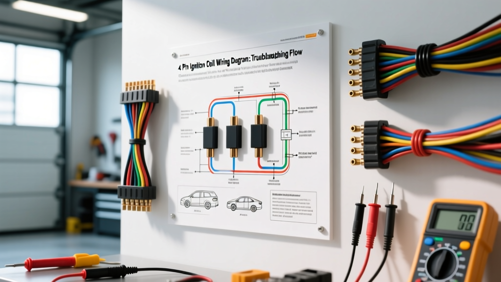
Understanding the 4-Pin Coil-on-Plug (COP) Architecture
Modern Coil-on-Plug (COP) ignition systems rely on precise electrical signals to deliver optimal spark energy under heavy load, such as when towing a trailer up a steep grade. While trailer wiring diagrams often dominate the focus of tow vehicle prep, the engine's ignition harness is equally critical. A failure in the primary ignition circuit will immediately result in a misfire, lost towing power, and potential catalytic converter damage. The standard 4-pin ignition coil connector is ubiquitous across many late-model inline-4 and V8 engines, including various Toyota, Lexus, and GM applications. Unlike older 2-pin or 3-pin setups that only handle power and a basic trigger, the 4-pin configuration introduces a dedicated feedback loop, allowing the Powertrain Control Module (PCM) to verify spark occurrence on a per-cylinder basis.
This guide provides a comprehensive, step-by-step troubleshooting flow for the 4-pin ignition coil wiring diagram. We will cover primary circuit verification, PCM signal analysis, and real-world wiring repair protocols to ensure your tow vehicle operates at peak electrical efficiency.
Standard 4-Pin Ignition Coil Pinout Reference
Before connecting your diagnostic tools, you must understand the specific function, wire gauge, and typical color coding of the 4-pin harness. While exact colors vary by manufacturer, the functional architecture remains consistent.
| Pin | Function | Typical Wire Color | AWG Size | Circuit Description |
|---|---|---|---|---|
| 1 | B+ (Power) | Pink/Black or Red | 14 AWG | Constant 12V-14V feed from the ignition relay or main fuse block. Requires high current capacity to charge the primary coil winding. |
| 2 | GND (Ground) | Black or Brown | 16 AWG | Dedicated chassis or PCM-controlled ground path. Must handle the primary current dump during the coil firing event. |
| 3 | IGT (Trigger) | White/Red or Yellow | 18-20 AWG | Ignition Trigger signal from the PCM. A low-amperage 5V square wave that commands the internal igniter to begin the dwell phase. |
| 4 | IGF (Feedback) | Blue or Green | 18-20 AWG | Ignition Feedback signal sent back to the PCM. Confirms that the primary circuit was successfully interrupted, verifying spark. |
Phase 1: Visual and Mechanical Inspection
Before probing any circuits with a multimeter, perform a rigorous physical inspection of the coil pigtail and harness. Engine bay heat cycles and vibration—especially when towing heavy loads over rough terrain—cause specific mechanical failures that mimic electrical shorts.
The Terminal Drag Test
Never use a standard paperclip or oversized probe to back-probe a COP connector. This causes 'terminal spread,' where the female terminal inside the harness connector is stretched beyond its yield point, resulting in an intermittent open circuit under vibration. Instead, use a dedicated T-pin or a specialized back-probe tool. Disconnect the coil harness and insert a known-good male terminal or a dedicated pin gauge into the female connector. You should feel a distinct, firm 'drag' or detent. If the pin slides in and out with zero resistance, the terminal is compromised and the entire pigtail must be replaced.
Harness Routing and Chafing
Inspect the harness where it passes through the valve cover brackets or near the exhaust manifold. Look for melted insulation or copper oxidation (a green/white crust inside the wire jacket). According to SAE J1128 standards for low-tension primary cable, insulation degradation significantly increases resistance and alters the signal capacitance, leading to phantom misfires.
Phase 2: Power and Ground Circuit Verification
The most common cause of a 'dead' coil is not a failed internal igniter, but a voltage-starved primary circuit. The coil requires a minimum of 11.5V at the B+ pin while cranking to saturate the primary winding adequately.
Step 1: B+ Voltage Drop Test
- Set your Digital Multimeter (DMM) to DC Volts.
- Connect the red probe to the battery positive terminal and the black probe to the B+ wire (Pin 1) at the coil harness connector (back-probed with ignition ON).
- A healthy circuit will show a voltage drop of less than 0.2V. If your DMM reads 1.5V or higher, you have excessive resistance in the power feed, likely due to a corroded ignition relay or a failing bulkhead connector.
Step 2: Ground Circuit Integrity
- Connect the DMM red probe to the battery positive terminal and the black probe to the GND wire (Pin 2) at the harness connector.
- With the ignition ON and the circuit active, the voltage drop must be below 0.1V.
- If the ground is PCM-controlled (common on some GM LS applications), the PCM will pull this circuit low to fire the coil. A high-resistance ground will cause the coil's internal switching transistor to overheat and fail prematurely, as it attempts to dissipate the inductive spike across a restricted path.
Phase 3: PCM Signal (IGT) and Feedback (IGF) Diagnostics
If power and ground are verified, the fault lies in the low-voltage logic circuits. Diagnosing the IGT and IGF circuits requires moving beyond a standard DMM and utilizing an automotive oscilloscope or a dedicated logic probe.
Analyzing the IGT (Trigger) Signal
The PCM sends a 5V square wave to the IGT pin. When the signal drops to approximately 0.5V, the coil's internal igniter turns ON, allowing current to flow through the primary winding (the 'dwell' phase). When the PCM pulls the signal back to 5V, the igniter turns OFF, collapsing the magnetic field and firing the spark plug.
- Dwell Time: At idle, dwell is typically 2.5 to 4.0 milliseconds. Under heavy load (e.g., towing at wide-open throttle), the PCM increases dwell time to maximize spark energy, sometimes up to 6.0 milliseconds.
- Waveform Anomalies: If the oscilloscope shows a rounded top on the 5V square wave rather than a sharp edge, you have excessive capacitance in the 18 AWG trigger wire, usually caused by parallel wiring repairs or water ingress in the harness.
Analyzing the IGF (Feedback) Signal
The IGF circuit is a critical diagnostic loop. If the PCM commands an IGT signal but does not receive an IGF confirmation, it will immediately cut fuel injection to that specific cylinder to protect the catalytic converter from unburned hydrocarbons. This triggers a P035X series Diagnostic Trouble Code (DTC). The IGF signal is typically a 5V pulse that occurs immediately after the spark event. A missing IGF signal with a confirmed good IGT signal almost always indicates an internal coil igniter failure, provided the 18 AWG feedback wire has continuity back to the PCM.
Step-by-Step Diagnostic Decision Matrix
Use this structured troubleshooting flow to isolate the root cause of the ignition failure rapidly.
| Symptom / DTC | Test Point | Expected Result | Action if Result Fails |
|---|---|---|---|
| P0351 (Coil 'A' Primary/Secondary Malfunction) | Pin 1 (B+) to Battery Ground | 12.4V (Key ON, Engine OFF) | Check ignition relay, main fuse, and 14 AWG power wire for opens. |
| P0351 (Coil 'A' Primary/Secondary Malfunction) | Pin 2 (GND) to Battery Positive | 12.4V (Key ON, Engine OFF) | Repair open in 16 AWG ground wire or clean chassis ground point. |
| Dead Cylinder, No DTC | Pin 3 (IGT) with Logic Probe | Pulsing light while cranking | Test continuity of trigger wire to PCM. If OK, suspect failed PCM driver. |
| P1300 (Igniter Circuit Malfunction) | Pin 4 (IGF) with Oscilloscope | 5V pulse after spark event | Verify IGF wire continuity. If wire is good, replace the ignition coil. |
Real-World Failure Modes and Wiring Repairs
When a wiring fault is isolated to the harness, proper repair techniques are non-negotiable. The AA1Car diagnostic library heavily emphasizes that improper splicing in high-frequency, low-voltage circuits like the IGT and IGF lines will introduce electromagnetic interference (EMI) and signal reflection.
Forbidden Repair Methods
- T-Taps and Saddle Splices: These pierce the wire insulation and rely on a small blade for contact. They introduce severe corrosion points and alter the wire's impedance, ruining the 5V square wave integrity.
- Twist-and-Tape: Electrical tape degrades rapidly in engine bay heat (often exceeding 220°F near the valve covers), leading to short circuits against the engine block.
Approved Automotive Splicing Protocol
- Strip and Clean: Use a precision wire stripper to remove 3/4 inch of insulation from the 18 AWG signal wire. Clean the exposed copper with isopropyl alcohol.
- Western Union Splice: Mechanically interlock the wires using a Western Union (Lineman's) splice to ensure the joint has physical strength before soldering.
- Rosin-Core Soldering: Apply heat and use 60/40 rosin-core solder. Acid-core plumbing solder will corrode the copper strands from the inside out.
- Dual-Wall Heat Shrink: Seal the repair using marine-grade, adhesive-lined (dual-wall) heat shrink tubing. The inner adhesive melts and seals out moisture and dielectric grease, while the outer wall provides abrasion resistance. Apply heat evenly until adhesive extrudes slightly from both ends.
Conclusion
Troubleshooting a 4-pin ignition coil wiring diagram requires a methodical approach that separates high-current primary circuits from low-voltage logic signals. By verifying the B+ and Ground circuits with voltage drop tests, analyzing the IGT and IGF waveforms with an oscilloscope, and executing military-grade wiring repairs, you can permanently resolve misfire issues. Whether you are diagnosing a daily driver or prepping a heavy-duty tow vehicle, respecting the specific AWG requirements and pin configurations of the COP system ensures reliable ignition performance under the most demanding thermal and electrical loads.