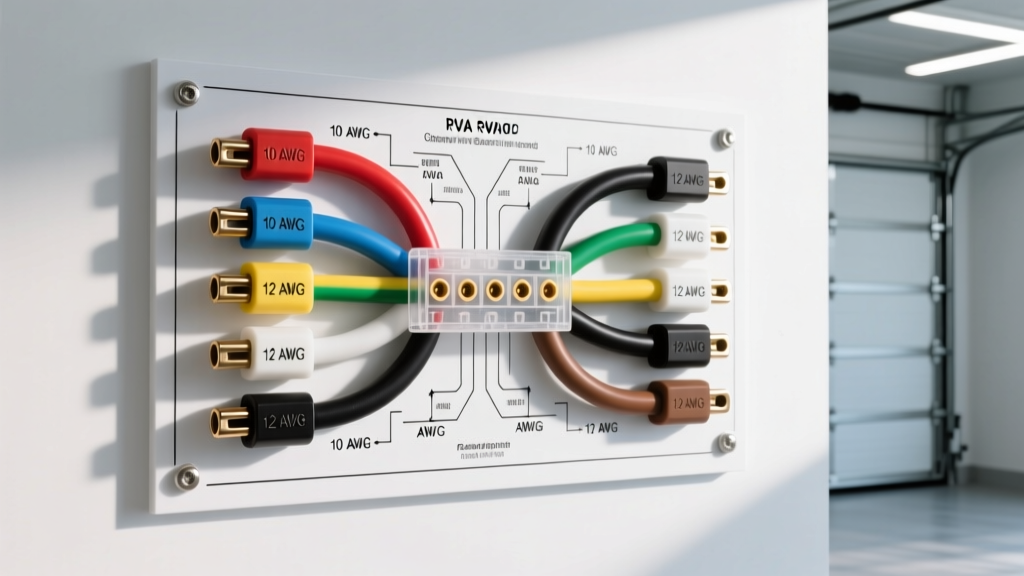
When sourcing a standard 7 pin RV wiring diagram online, most guides provide a superficial overview of wire colors and basic pin functions. However, for heavy-duty towing, custom trailer builds, or integrating advanced proportional brake controllers, a basic color chart is insufficient. As an automotive electrical specialist, I approach the 7-way RV connector not just as a lighting harness, but as a high-current power distribution node and a pulse-width modulated (PWM) data link. This advanced technical deep dive explores the Recreation Vehicle Industry Association (RVIA) standards, American Wire Gauge (AWG) voltage drop calculations, and the electromechanical realities of trailer braking systems.
The RVIA 7-Way Blade Pinout Matrix
While commercial trucks often utilize the round 7-pin connector governed by the SAE J560 standard, the RV and light-duty towing industry relies on the RVIA 7-way blade connector. Misunderstanding the difference between these two standards is a common catalyst for catastrophic wiring failures. Below is the definitive pinout matrix for the RVIA 7-way blade, including recommended minimum AWG sizing based on continuous amperage loads and voltage drop tolerances over a standard 25-foot trailer tongue run.
| Pin Position | Function | RVIA Standard Color | Min. AWG (25ft Run) | Max Continuous Load |
|---|---|---|---|---|
| 1 (Top Left) | Tail / Marker Lights | Brown | 12 AWG | 15A |
| 2 (Top Right) | Right Turn / Stop | Green | 12 AWG | 15A |
| 3 (Bottom Left) | Ground (Chassis Return) | White | 8 AWG | 40A+ |
| 4 (Bottom Right) | Electric Brakes | Blue | 10 AWG | 20A |
| 5 (Center Left) | Left Turn / Stop | Yellow | 12 AWG | 15A |
| 6 (Center Right) | 12V Auxiliary / Battery Charge | Black | 8 AWG | 30A |
| 7 (Center Bottom) | Reverse Lights / Aux | Purple | 14 AWG | 10A |
Advanced AWG Sizing and Voltage Drop Calculations
The most frequent failure mode in custom 7 pin RV wiring diagram implementations is undersizing the 12V Auxiliary (Black) and Electric Brake (Blue) circuits. Many pre-fabricated harnesses utilize 12 AWG wire for all circuits to cut manufacturing costs. While 12 AWG is sufficient for LED marker lights drawing mere milliamps, it is entirely inadequate for charging a deep-cycle RV battery bank or actuating multiple electric brake magnets simultaneously.
The Mathematics of Voltage Drop
Electric trailer brakes typically feature four 10-ohm or 12-ohm magnets wired in parallel, resulting in a total circuit resistance of roughly 2.5 to 3.0 ohms. At 12 volts, this draws approximately 4 to 5 amps per axle. On a triple-axle toy hauler, the brake circuit can pull upwards of 15 amps continuously during a panic stop. Using the standard voltage drop formula:
VD = (2 × L × R × I) / 1000
Where L is the one-way length of the wire (in feet), R is the resistance per 1000 feet of the specific AWG, and I is the current in amps. For a 30-foot run of 12 AWG copper wire (1.588 ohms per 1000 ft) carrying 15 amps, the voltage drop is 1.42 volts. This means your brake magnets are only receiving 10.58 volts, significantly reducing braking torque and causing the brake controller to falsely read a circuit fault. Upgrading the Blue wire to 10 AWG (0.9989 ohms per 1000 ft) reduces this drop to 0.89 volts, ensuring optimal magnetic actuation. For comprehensive wire resistance tables and harness routing techniques, consult etrailer's advanced wiring FAQ.
Brake Controller Integration and PWM Signal Routing
Modern proportional brake controllers do not send a steady DC voltage down the Blue wire. Instead, they utilize Pulse Width Modulation (PWM) to simulate variable voltage. By rapidly switching the 12V source on and off (often at frequencies exceeding 200 Hz), the controller varies the duty cycle to control the electromagnetic force applied to the brake shoes.
Troubleshooting PWM Feedback and Inductive Kickback
Because electric brake magnets are highly inductive loads, the rapid switching of a PWM signal generates severe inductive kickback (voltage spikes). If your 7 pin RV wiring diagram implementation lacks proper flyback protection, these spikes can travel back through the Blue wire and destroy the solid-state relays inside the tow vehicle's brake controller. When building a custom harness, integrate a high-amperage flyback diode or a transient voltage suppression (TVS) diode array parallel to the brake magnet coils on the trailer side. This clamps the reverse voltage spike, protecting the sensitive microcontrollers in the tow vehicle.
PWM Signal Loss Decision Tree
If your proportional brake controller displays a flashing red light or fails to output voltage during a manual slide test, follow this diagnostic sequence:
- Step 1: Measure DC Output. Set your multimeter to DC Volts. With the manual slide fully engaged, probe the Blue wire at the 7-way plug. A reading of 11.5V-12.5V indicates the controller is outputting correctly.
- Step 2: Check for PWM Duty Cycle. If using an oscilloscope or an advanced automotive multimeter with duty cycle functions, verify the square wave. A healthy controller will show a 90-95% duty cycle at max manual slide.
- Step 3: Inspect the Trailer Side. Disconnect the trailer. Measure resistance across the Blue and White pins on the trailer plug. You should read between 2.0 and 4.0 ohms depending on the number of axles. An 'OL' (Open Line) reading indicates a severed Blue wire or a blown thermal fuse on the brake magnet.
- Step 4: Verify Flyback Diode. If the controller repeatedly resets or throws a short-circuit code the moment brakes are applied, inspect the trailer-side wiring for a missing or shorted flyback diode.
Grounding Topologies: Chassis vs. Dedicated Return
The White wire (Pin 3) is the most critical circuit in the entire 7-way connector. Standard wiring diagrams instruct you to ground the White wire to the trailer's steel chassis. In a controlled laboratory environment, this works. In the real world, trailer chassis grounds are notorious for causing parasitic draws, flickering lights, and brake controller 'S.H.' (short circuit) error codes.
The Galvanic Corrosion Factor
Many modern RVs and trailers utilize aluminum frames or feature extensive galvanic isolation tape between steel axles and aluminum crossmembers. Relying on the chassis to return 30+ amps of combined lighting and brake current back to the tow vehicle is an electrical engineering fallacy. The connection points will inevitably suffer from galvanic corrosion, increasing resistance and creating a voltage differential.
Expert Recommendation: Treat the White wire as a dedicated current return path, not merely a ground. Run an 8 AWG or even 6 AWG White wire from the 7-way plug directly to the main negative bus bar of the trailer's electrical system, completely bypassing the chassis. On the tow vehicle side, ensure the White wire terminates directly at the battery negative terminal or the primary chassis ground stud, rather than relying on a sheet-metal screw into the truck bed.
To scientifically validate your ground return path, use a digital milliohm meter. Place one probe on the trailer's main negative bus bar and the other on the White wire pin at the disconnected 7-way plug. A reading above 5 milliohms indicates unacceptable resistance, usually caused by undersized wire or poor crimp terminations. In high-amperage scenarios, even 10 milliohms of resistance will generate localized heat and voltage drop, starving the electric brakes of necessary current.
Connector Weatherproofing and Terminal Crimping
The physical termination of the 7-way plug dictates the longevity of the harness. Soldering wires directly into the molded 7-way plug pins is a common DIY mistake. Solder is brittle and lacks the tensile strength to withstand the constant vibration and mechanical shock of highway towing, leading to micro-fractures and intermittent shorts inside the plug housing.
- Crimp vs. Solder: Always use closed-barrel, nylon-insulated crimp terminals with a ratcheting crimper. The cold-weld mechanical connection of a proper crimp outperforms solder in high-vibration automotive environments.
- Dielectric vs. Conductive Grease: Apply a copper-based anti-oxidant conductive grease to the crimp barrels before compressing them to prevent internal strand corrosion. However, apply a silicone-based dielectric grease only to the exterior mating surfaces of the 7-way plug to repel moisture and prevent galvanic oxidation between the brass tow-vehicle pins and the steel trailer connector.
- Strain Relief: Utilize an Adel clamp (cushioned P-clamp) within 3 inches of the 7-way plug to absorb mechanical tension, ensuring that any pulling force on the harness is transferred to the trailer tongue rather than the delicate brass terminal pins.
Mastering the 7 pin RV wiring diagram requires looking beyond basic color codes. By applying rigorous AWG voltage drop calculations, understanding PWM inductive loads, and implementing dedicated ground return topologies, you can build a trailer electrical system that rivals OEM heavy-duty specifications. For further reading on commercial heavy-duty standards, review the RVIA technical bulletins and ensure your custom builds comply with all federal DOT lighting and braking mandates.