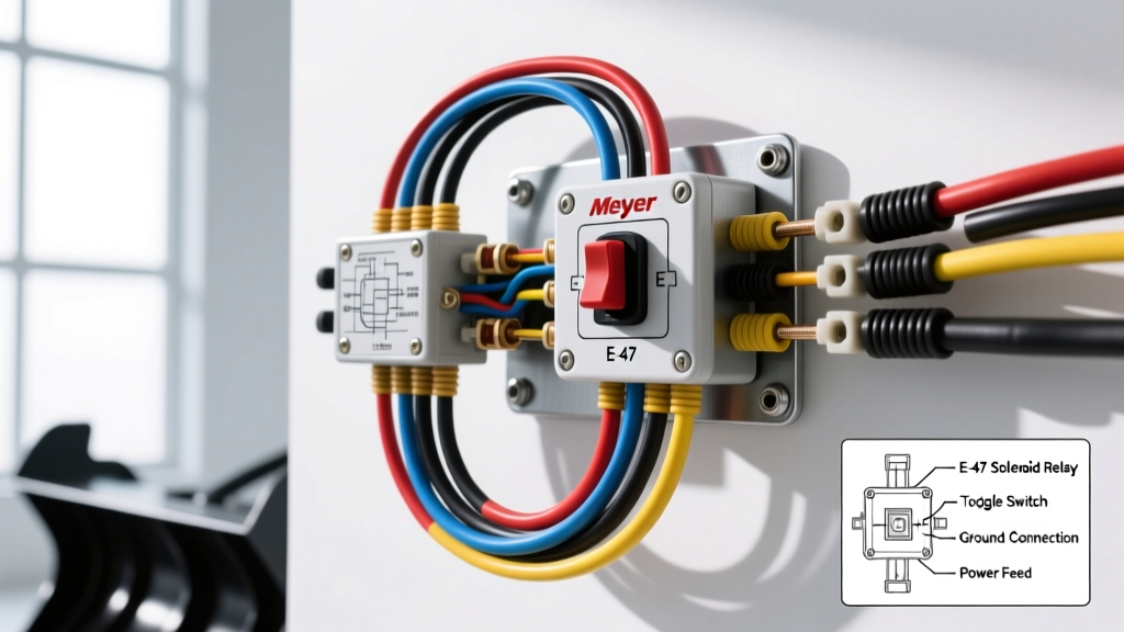
Why Bypass the Joystick? The Case for a Toggle Switch Panel
Standard Meyer joystick controllers are notorious for failing in harsh winter conditions. Internal PCB corrosion, pinched control cables, and failing potentiometers can leave a plow operator stranded with a stuck blade. For fleet managers and owner-operators, building a custom toggle switch panel is a bulletproof, cost-effective alternative or backup to the factory controller. This guide provides a comprehensive Meyer snow plow wiring harness diagram and practical installation steps to wire a manual toggle switch panel directly to the Meyer E-47 or E-60 hydraulic pump solenoids.
Unlike simple 12V lighting circuits, snow plow solenoid coils are highly inductive loads. Wiring toggle switches directly to the solenoids without automotive relays will result in severe inductive kickback, arcing across the switch contacts and destroying them within weeks. This guide details the proper relay-driven architecture required for a reliable, heavy-duty toggle switch panel.
Meyer E-47 / E-60 Solenoid Valve Specifications
Before cutting into your Meyer Products wiring harness, you must understand the hydraulic pump's solenoid coil mapping. The standard Meyer E-47 and E-60 pumps utilize a three-coil system to direct hydraulic fluid for lifting and angling. The drop (down) function is typically achieved via gravity when the lift coil is de-energized and the drop valve is unseated by internal hydraulic pressure, though some specialized setups use a dedicated drop coil.
| Function | Coil ID | Standard Wire Color | Resistance (Ohms) | Avg Amp Draw |
|---|---|---|---|---|
| Lift (Up) | Coil A | Black with White Tracer | 1.5 - 2.0 Ω | 8 - 11 Amps |
| Angle Left | Coil B | Black with Green Tracer | 1.5 - 2.0 Ω | 8 - 11 Amps |
| Angle Right | Coil C | Black with Orange Tracer | 1.5 - 2.0 Ω | 8 - 11 Amps |
| Common Ground | N/A | Solid Black | N/A | N/A |
Required Components and AWG Wire Sizing
Adhering to SAE J1128 standards for low-tension primary cable is critical for under-hood routing where temperatures fluctuate wildly and exposure to road salt is guaranteed. Cross-linked polyethylene (XLPE) insulation is highly recommended over standard PVC for its superior resistance to abrasion and heat.
| Component | Specification | Purpose |
|---|---|---|
| Toggle Switches | 20A SPST (Single Pole Single Throw) | Low-amperage trigger control for relays |
| Relays | 30A Bosch-Style SPDT (ISO Mini) | Handles high-current inductive solenoid loads |
| Flyback Diodes | 1N4001 or 1N4004 | Suppresses inductive voltage spikes |
| Main Power Wire | 8 AWG XLPE | Battery to Fuse Block / Relay Block |
| Solenoid Feed Wire | 10 AWG XLPE | Relay Pin 87 to Meyer Solenoid Coils |
| Switch Trigger Wire | 14 AWG GXL | Toggle switch to Relay Pins 85/86 |
| Circuit Protection | 15A ATO Fuses (per circuit) | Protects solenoid feed wiring |
Step-by-Step Toggle Switch Panel Wiring Guide
Step 1: Power Distribution and Circuit Protection
Do not draw power from the vehicle's ignition switch or accessory circuits; the combined draw of two solenoids actuating simultaneously (e.g., lifting and angling) can exceed 20 amps, which will melt factory accessory wiring. Run an 8 AWG wire directly from the truck battery's positive terminal. Install a 60A Maxi-Fuse or circuit breaker within 18 inches of the battery. Route this main power feed into the cab or to a protected relay box under the hood, terminating it into a fused distribution block. From the distribution block, run 10 AWG wires with 15A ATO fuses to Pin 30 of each of your three relays.
Step 2: Wiring the Relays and Flyback Diodes
According to the Littelfuse Automotive Relay Guide, managing inductive kickback is mandatory when switching solenoid coils. When the toggle switch is turned off, the collapsing magnetic field in the Meyer solenoid generates a reverse voltage spike that can exceed 100V. This spike travels back through the wiring and will arc across your toggle switch contacts, welding them shut or causing rapid carbon buildup.
Relay Pinout Configuration:
- Pin 30: Fused 12V+ Main Power In (from distribution block).
- Pin 87: 12V+ Power Out (10 AWG wire running to the Meyer Solenoid Coil).
- Pin 86: 12V+ Trigger Power In (from the toggle switch).
- Pin 85: Trigger Ground (to chassis ground or common ground bus).
Diode Installation: Solder a 1N4001 flyback diode across the relay coil pins (85 and 86). The silver band (cathode) of the diode MUST point toward Pin 86 (positive trigger), and the anode toward Pin 85 (ground). This creates a safe loop for the inductive spike to dissipate harmlessly within the relay coil, saving your toggle switches and vehicle ECU.
Step 3: Switch Panel and Trigger Routing
Mount your SPST toggle switches in a weatherproof panel in the cab. Run a 14 AWG 12V+ ignition-switched wire to the common input terminal of all three toggle switches. The output terminal of each switch will run via 14 AWG wire through the firewall to Pin 86 of its respective relay. This ensures the plow panel powers down when the truck is turned off, preventing parasitic battery drain.
Step 4: Routing to the Meyer Plow Harness
You have two options for integrating with the Meyer harness. Option A (Non-Destructive): Purchase a Meyer 13-pin motor harness pigtail adapter, splice your 10 AWG relay outputs to the corresponding Black/White, Black/Green, and Black/Orange wires, and plug it in-line. Option B (Direct Pump Connection): Remove the pump cover, disconnect the factory solenoid spades, and attach your 10 AWG ring terminals directly to the solenoid studs. Ensure you apply dielectric grease to all connections to prevent galvanic corrosion from road salt. The common Black ground wire must be securely bolted to the pump motor housing or a dedicated chassis ground, torqued to 15 ft-lbs to prevent voltage drop.
Meyer Snow Plow Wiring Harness Diagram: Schematic Mapping
Visualize the circuit flow for the Lift (Coil A) function as follows:
Battery (+) --> 60A Breaker --> 8 AWG Main Feed --> Fuse Block --> 15A Fuse --> 10 AWG --> Relay Pin 30
Relay Pin 87 --> 10 AWG --> Meyer Harness Black/White Wire --> Coil A Solenoid
Coil A Solenoid Internal Ground --> Pump Housing --> Chassis Ground --> Battery (-)
Ignition (+) --> 14 AWG --> Toggle Switch A --> 14 AWG --> Relay Pin 86
Relay Pin 85 --> 14 AWG --> Chassis Ground
Replicate this exact architecture for Coil B (Black/Green) and Coil C (Black/Orange). Never combine the ground paths of the solenoid coils; keep them isolated to the pump housing to prevent back-feeding through the controller ground circuit.
Troubleshooting Decision Tree
| Symptom | Multimeter Test | Probable Cause & Fix |
|---|---|---|
| Toggle switch clicks relay, but plow does not move. | Check voltage at Relay Pin 87 while switch is ON. | Blown 15A ATO fuse or broken 10 AWG wire. Replace fuse and check for pinched harness. |
| Relay clicks, voltage is present at solenoid stud, pump motor doesn't run. | Check voltage at main motor cable (large red wire) during lift command. | Failed motor solenoid (under hood) or bad pump motor ground. Clean pump ground, torque to 15 ft-lbs. |
| Toggle switch gets extremely hot and melts. | Inspect switch contacts for pitting/carbon. | Missing flyback diode or switch wired directly to solenoid without relay. Install 30A relay and 1N4001 diode. |
| Plow drifts down slowly when lifted. | Check for 12V+ at Coil A when switch is OFF. | Leaking hydraulic drop valve or stuck relay contacts. Tap relay to free contacts, replace if welded. |
Final Inspection and Weatherproofing
Once all connections are verified with a multimeter, apply a liberal coating of silicone dielectric grease to all toggle switch terminals and relay spades. Use adhesive-lined heat shrink tubing on all under-hood splices. A properly executed toggle switch panel wiring job using this Meyer snow plow wiring harness diagram will outlast three factory joysticks, providing reliable, high-amperage hydraulic control for years of heavy commercial plowing.