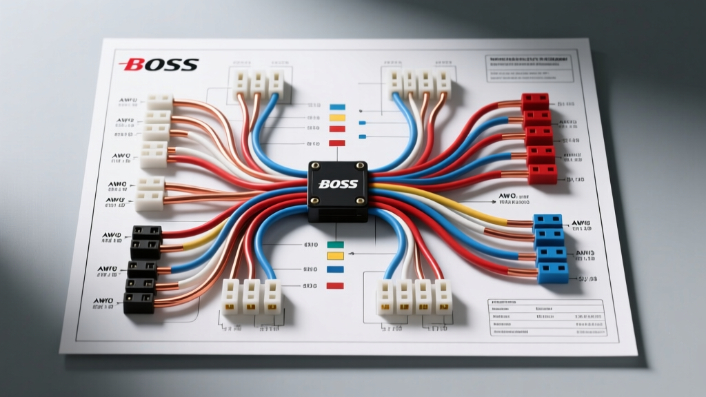
Introduction to Boss Multiplex Smart Controller (MSC) Systems
Modern snow plow electrical systems have evolved far beyond simple relay-and-switch setups. Today, the industry standard for heavy-duty commercial and municipal fleets is multiplex wiring. If you are searching for a comprehensive wiring diagram for Boss plow multiplex systems, you are likely dealing with the Boss Multiplex Smart Controller (MSC) architecture. Unlike older systems that required a dedicated, heavy-gauge wire for every single hydraulic valve and lighting circuit, multiplex systems utilize a Controller Area Network (CAN) data bus to transmit signals. This drastically reduces the physical size of the harness, minimizes voltage drop, and allows for advanced onboard diagnostics.
However, the reduced wire count does not mean the installation is less critical. A single pinched data line or improperly crimped 2 AWG power feed can shut down the entire system. This practical how-to guide will walk professional installers and advanced DIYers through the exact specifications, pin configurations, and routing protocols required to execute a flawless truck-side harness installation for a Boss MSC system.
Pre-Installation Preparation and Safety Protocols
Before unrolling the harness or consulting the schematic, you must prepare the vehicle and your workspace. The electrical demands of a Boss V-plow or heavy-duty straight blade can exceed 150 amps during peak hydraulic stall conditions (such as hitting a frozen windrow at an angle).
- Battery Disconnect: Always disconnect the negative battery terminal first to prevent accidental short circuits while routing the main power feeds.
- Corrosion Prevention: Procure a high-quality dielectric grease specifically formulated for multiplex pins (Boss Part #MSC05065 or equivalent). Standard chassis grease will interfere with the low-voltage data signals.
- Tooling: You will need a hydraulic crimper with hex dies for 2 AWG terminals, a heat gun with a reflector nozzle for adhesive-lined heat shrink, and a digital multimeter capable of measuring millivolt drops.
- Wire Selection: All primary power cables must meet or exceed SAE J1128 Type SXL specifications for high-temperature, cross-linked polyethylene insulation.
Understanding the Wiring Diagram for Boss Plow MSC Systems
The core of the Boss multiplex architecture relies on the 13-pin truck-to-plow connector. When reading the wiring diagram for Boss plow setups, you will notice that the harness is split into three main segments: the high-current power feed, the vehicle lighting integration (often utilizing ISO modules or direct CAN integration depending on the truck's OEM network), and the multiplex data/power umbilical.
Below is the standard 13-pin MSC connector pinout reference chart. Always verify against the specific literature pack included with your exact MSC harness kit, as minor revisions occur between model years.
| Pin Number | Wire Color | Circuit Function | AWG / Specification |
|---|---|---|---|
| 1 | Red | Main Battery Feed (+12V) | 2 AWG (Stranded Copper) |
| 2 | Black | System Ground | 2 AWG (Stranded Copper) |
| 3 | Blue | CAN Data High (Multiplex) | 16 AWG (Shielded Twisted Pair) |
| 4 | White | CAN Data Low (Multiplex) | 16 AWG (Shielded Twisted Pair) |
| 5 | Green | Left Turn / Marker Signal | 14 AWG |
| 6 | Brown | Right Turn / Marker Signal | 14 AWG |
| 7 | Yellow | Headlamp High Beam Feed | 14 AWG |
| 8 | Purple | Headlamp Low Beam Feed | 14 AWG |
| 9 | Orange | Ignition Switched Power (Accessory) | 14 AWG |
| 10 | Gray | Plow Marker / Clearance Lights | 14 AWG |
| 11 | Light Blue | Diagnostic / Wake-Up Signal | 18 AWG |
| 12 | Pink | Spare / Auxiliary Circuit | 14 AWG |
| 13 | Red/White Stripe | Secondary Battery Feed (High Draw) | 2 AWG (Stranded Copper) |
Step-by-Step Truck-Side Harness Installation
Step 1: High-Current Power and Solenoid Connections
The hydraulic power unit (HPU) motor requires massive current surges. Begin by routing the 2 AWG Red and Black cables from the battery tray to the solenoid mounting location. Pro-Tip: Do not use the vehicle's frame as a ground return path for the plow. The high amperage will overwhelm standard body-to-frame ground straps, leading to erratic PCM behavior or fried alternator diodes. Always run a dedicated 2 AWG ground wire directly from the solenoid base to the negative battery terminal.
Crimp the 2 AWG ring terminals using a hydraulic press to ensure a gas-tight connection. Seal the crimp barrel with 3M MDT adhesive-lined heat shrink. Mount the heavy-duty continuous solenoid (rated for minimum 150A continuous / 300A intermittent) on a clean, painted surface in the engine bay, away from exhaust manifolds.
Step 2: Routing the Multiplex Umbilical
The 13-pin multiplex cable contains sensitive CAN data lines (Pins 3 and 4). These lines operate on low-voltage differential signaling. When routing the harness through the engine bay, maintain a minimum clearance of 6 inches from high-voltage ignition coils, aftermarket stereo amplifiers, and alternator output wires to prevent Electromagnetic Interference (EMI). If crossing a high-current wire is unavoidable, do so at a strict 90-degree angle.
Step 3: Firewall Penetration and Cab Routing
Locate an existing, unused knockout on the vehicle's firewall or utilize a thick rubber grommet shared with the OEM hood release cable. Never drill a bare metal hole and pull the harness through; vibration will strip the insulation and short the CAN bus to the chassis, instantly throwing the MSC module into protective shutdown mode. Use a fish tape to pull the cab-side connector under the dash, ensuring you leave a 4-inch "drip loop" on the engine side so condensation cannot track back into the firewall.
Step 4: Controller Integration and OEM Lighting
Connect the MSC receiver module under the dash. For modern trucks (2015+ GM, Ford, and Ram), you will likely interface with the vehicle's CAN-bus or LIN-bus via an OEM-specific isolation module. This module reads the truck's headlamp and turn signal data without splicing directly into the factory wires, preventing voided warranties and hyper-flash issues. Secure the module with heavy-duty zip ties, ensuring it is suspended above the HVAC drain tube to avoid water damage.
Common Failure Modes and Troubleshooting Decision Trees
Even with a perfect installation, environmental factors can cause issues. Use this diagnostic tree when referencing your wiring diagram for Boss plow systems to isolate faults.
Symptom: Plow Lights Flash, but Hydraulics Do Not Engage
- Check the Main Power Feed: Use a multimeter to measure voltage drop across the 2 AWG Red cable while a helper attempts to raise the blade. A drop greater than 0.5V indicates a failing crimp or corroded battery terminal.
- Inspect the Solenoid Trigger: Verify that the MSC module is sending +12V to the solenoid's small "S" terminal when the raise button is pressed. If present, but the solenoid doesn't click, the solenoid coil is burned out.
- Verify Ground Integrity: Check the dedicated 2 AWG ground. If the plow is attempting to ground through the hitch chains, you will see arcing and the MSC will register a ground fault.
Symptom: Controller Displays "Comm Error" or "Data Link Fault"
- Inspect Pins 3 and 4: Disconnect the 13-pin connector. Inspect the Blue and White pins for pushed-back terminals or corrosion.
- Test for Shorts: With the harness unplugged at both ends, use an ohmmeter to check continuity between Pin 3 (CAN High) and chassis ground. It should read infinite resistance (OL). Any continuity indicates a pinched data wire in the engine bay.
- Check the Drip Loop: Ensure water has not wicked into the cab-side connector via capillary action. If moisture is present, clean with electrical contact cleaner and pack with Boss MSC05065 dielectric grease.
Authoritative References and Further Reading
Proper installation requires adherence to both manufacturer specifications and broader automotive electrical standards. Always consult the latest literature provided by the manufacturer. For comprehensive installation manuals, schematics, and multiplex diagnostic codes, refer to the official Boss Snowplows Literature Library. Additionally, all wire selection and crimping standards referenced in this guide are derived from the SAE J1128 Low Tension Primary Cable Standard, ensuring your harness can withstand the extreme under-hood temperatures and chemical exposures inherent to winter maintenance operations.