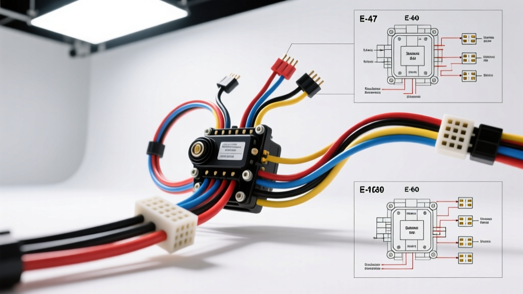
Decoding the Meyers Plow Wiring Diagram: E-47 and E-60 Systems
When servicing, installing, or troubleshooting a Meyer snow plow, relying on a generic or outdated schematic is a recipe for electrical failure and hydraulic downtime. The specific Meyers plow wiring diagram for your exact power unit—whether it is the legendary E-47, the high-capacity E-60, or the modern Fleet Master system—dictates the routing, wire gauge, and pinout of your harness. In this complete walkthrough, we dissect the 3-plug multiplex system, the hydraulic pump motor power circuit, and the 11-pin control connector to ensure your plow operates flawlessly in sub-zero conditions. Proper adherence to these wiring specifications prevents voltage drop, solenoid burnout, and erratic valve operation.
The High-Amperage Power Circuit: Motor and Solenoid Routing
The heart of the Meyer electrical system is the high-amperage power circuit. The hydraulic pump motor can draw upwards of 180 amps under peak hydraulic pressure, such as when the blade impacts a frozen windrow or encounters heavy, wet snow. To support this massive current draw, the main power feed from the truck battery to the plow solenoid must utilize a minimum of 4 AWG, though 2 AWG stranded copper is highly recommended for cable runs exceeding 8 feet.
According to SAE J1128 standards for low-tension primary cable, the insulation must withstand high engine bay temperatures and resist road salt corrosion. The main solenoid is typically an intermittent-duty 12V relay rated for 150A continuous and 600A inrush current. The motor ground is equally critical; Meyer requires a dedicated 4 AWG ground cable routed directly from the motor housing grounding lug to the vehicle chassis or battery negative terminal. Never rely on the pump motor mounting bolts or the hydraulic fluid for the primary ground path, as paint, powder coating, and fluid dielectric properties will cause severe voltage drop. Torque the motor lugs to 35-45 in-lbs and apply a high-quality dielectric grease to prevent galvanic corrosion at the terminal.
Understanding the 3-Plug Multiplex Harness Configuration
Modern Meyer plows utilize a 3-plug configuration that separates the electrical loads into three distinct circuits: Power, Control, and Lighting. This separation ensures that a short in the lighting harness will not disable the hydraulic pump motor, a critical safety feature during storm operations.
- Power Plug (2-Pin): Handles the heavy 4 AWG motor power and ground. Features heavy-duty weather-pack seals and locking tabs.
- Control Plug (11-Pin or 12-Pin): Carries low-amperage 14-16 AWG signals from the in-cab Touch-Turn controller to the plow-mounted solenoids and hydraulic valves.
- Lighting Plug (12-Pin): Routes headlamp, turn signal, and marker light circuits, often interfacing with a Smart Arrow Multiplex (S.A.M.) module on newer trucks.
Step-by-Step 11-Pin Control Harness Walkthrough & Pinout
The 11-pin control connector is the nervous system of the plow. It transmits the driver's joystick or Touch-Turn commands to the hydraulic valve coils (A, B, and C). A miswired control plug will result in reversed angles, failure to lift, or blown fuses on the truck's ignition circuit. Below is the standard pinout for the Meyer E-47/E-60 11-pin control harness.
| Pin | Wire Color | Function / Circuit | AWG | Diagnostic Note |
|---|---|---|---|---|
| 1 | Red | 12V Switched Ignition | 14 | Must read 12V+ when truck is ON. Powers controller logic. |
| 2 | Black | Control Ground | 14 | Must have less than 0.2V drop to battery negative. |
| 3 | White | Motor Solenoid Trigger | 14 | Provides ground path to activate the main 150A pump relay. |
| 4 | Green | Valve B Coil (Lift/Angle) | 16 | Activates the B valve for lift and specific angle functions. |
| 5 | Brown | Valve C Coil (Drop/Angle) | 16 | Activates the C valve to lower the blade via gravity. |
| 6 | Blue | Valve A Coil (Left/Right) | 16 | Activates the A valve for lateral angling of the moldboard. |
| 7 | Orange | Controller Data / Multiplex | 18 | Used on newer digital controllers for PWM signal transmission. |
| 8 | Yellow | Float / Drop Speed | 16 | Modulates the drop valve for float mode operation. |
| 9 | Purple | Accessory / Aux Trigger | 16 | Reserved for auxiliary lighting or heated mirror integration. |
| 10 | Gray | Diagnostic Feedback | 18 | Signals controller if a valve coil is open or shorted. |
| 11 | Black/White | Secondary Ground | 14 | Redundant ground for high-reliability multiplex modules. |
Lighting Harness and the S.A.M. Module Integration
For trucks equipped with multiplex lighting systems (common in post-2010 GM, Ford, and Ram heavy-duty models), the Meyer lighting harness must interface with a Smart Arrow Multiplex (S.A.M.) module or a similar Bosch-style smart relay isolator. The 12-pin lighting plug carries standard HB4/HB5 headlamp signals, but the truck's Body Control Module (BCM) requires specific resistance loads to prevent bulb-out warnings. The S.A.M. module simulates the incandescent bulb resistance, drawing approximately 2.5 amps per circuit, and triggers the plow's LED or halogen headlamps via heavy-duty internal MOSFETs. When wiring the lighting plug, ensure the red/white and black/white tracer wires are correctly mapped to the left and right turn signals, as reversing these will cause the plow lights to flash out of sequence with the truck.
Real-World Troubleshooting: Voltage Drop and Coil Resistance
When a Meyers plow wiring diagram indicates a circuit is complete, but the plow fails to operate, the issue is almost always excessive resistance. To diagnose this, abandon the standard continuity test and perform a live voltage drop test using a Digital Multimeter (DMM).
Testing the Main Power Circuit
Set your DMM to DC Volts. Place the red probe on the positive battery terminal and the black probe on the motor-side terminal of the main solenoid. Have an assistant activate the plow motor. A reading above 0.5V indicates a failing cable, a corroded battery terminal, or an undersized wire gauge. Next, test the ground side by placing the red probe on the motor housing (bare metal) and the black probe on the battery negative terminal. Again, a drop exceeding 0.5V necessitates cleaning the chassis ground point or replacing the 4 AWG ground strap.
Testing Hydraulic Valve Coils
If the plow lifts but will not angle left or right, the Valve A coil or its trigger wire is suspect. Disconnect the 11-pin control plug and set your DMM to Ohms (Ω). Measure the resistance across Pin 6 (Blue wire) and Pin 2 (Black ground). A healthy Meyer hydraulic valve coil should read between 12 and 18 ohms at room temperature. If the DMM reads 'OL' (Open Line), the internal copper windings of the coil have broken, requiring a complete valve coil replacement. If it reads near 0 ohms, the coil has shorted internally, which will instantly blow the controller's internal 10A fuse. Always apply a dab of silicone dielectric grease to the 11-pin connector before mating it to the plow harness to prevent moisture ingress and subsequent copper oxidation.
Maintenance and Connector Preservation
The harsh environment of snow plowing exposes all electrical connections to highly corrosive calcium chloride and magnesium chloride brines. At the end of every season, or at minimum every 30 days during heavy salting operations, disconnect all three harness plugs. Wash the pins with an electrical contact cleaner to dissolve salt residue, inspect the rubber weather-pack seals for micro-tears, and reapply a marine-grade dielectric grease. For the 4 AWG power plugs, check the locking tab tension; if the plug can be removed without depressing the latch, the terminal retention clips have fatigued and the entire connector housing must be replaced to prevent arcing and melting under the 180-amp load.