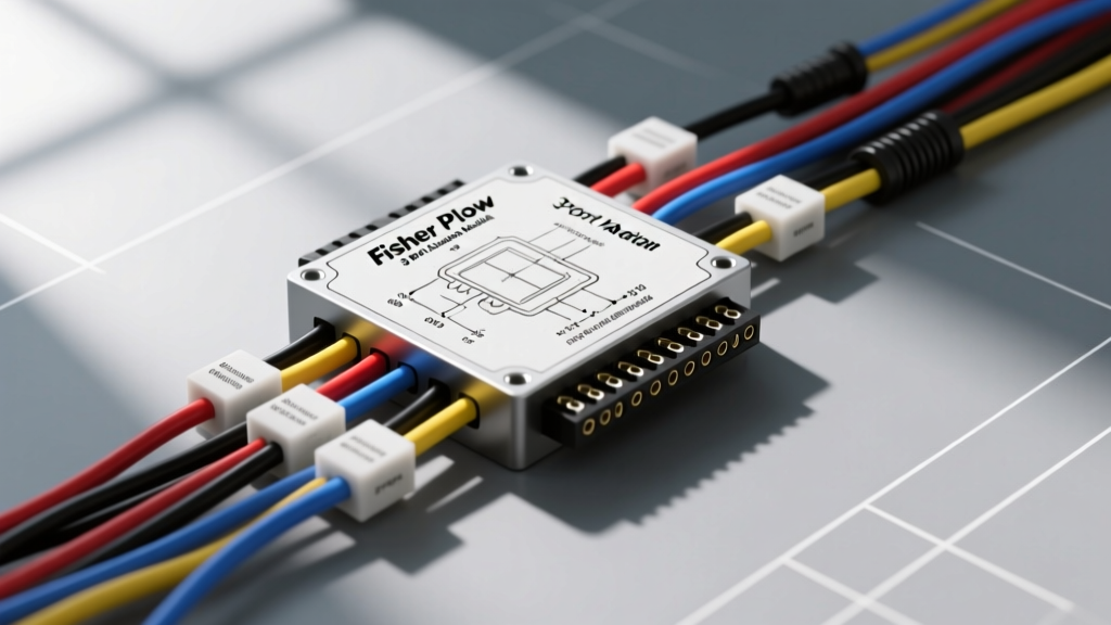
Introduction to Fisher Multiplex V Isolation Systems
The transition from legacy 4-port systems to the Fisher Multiplex V 3-port architecture marked a significant evolution in snow plow electrical engineering. For fleet managers, independent operators, and automotive electrical technicians, understanding the Fisher plow 3 port isolation module wiring diagram is critical for accurate diagnostics, seamless harness routing, and proper component selection. Unlike older relay-based setups, the Multiplex V system utilizes a Controller Area Network (CAN) bus to communicate between the in-cab controller and the plow-mounted hydraulic valves. This reduces the physical wire count, minimizes voltage drop, and significantly improves response times for blade angling and lifting. However, it also means that selecting the correct replacement isolation module requires precise matching of truck-side headlamp harnesses and control port configurations. This guide serves as a comprehensive product comparison and technical wiring reference to ensure your snow plow electrical system operates flawlessly in extreme winter conditions.
Product Comparison: Selecting the Right Fisher Isolation Module
When sourcing a replacement or upgrading an older truck harness, selecting the correct isolation module is the most common point of failure. Fisher Engineering offers several 3-port Multiplex V modules tailored to specific headlamp configurations and plow models (e.g., Minute Mount 2, Xtreme Duty). Below is a comparison matrix to guide your selection process based on OEM headlamp bulb types and port architecture.
| Part Number | System Type | Headlamp Harness | Best Application |
|---|---|---|---|
| 26345 | 3-Port Multiplex V | HB5 / 9007 | Standard Duty / MVP (Older GM/Ford) |
| 29464 | 3-Port Multiplex V | H11 / H13 | Late Model GM / Ford / RAM (Projector/Halogen) |
| 29047 | 4-Port Legacy | HB5 / 9007 | Pre-2010 setups (Requires 4-port truck harness) |
| 29521 | 3-Port Multiplex V | HB7 / 9005 | Specific Toyota / Nissan applications |
Selection Rule of Thumb: Never attempt to adapt a 4-port legacy module (like the 29047) to a 3-port Multiplex V truck harness using splice connectors. The CAN bus signaling requires specific termination resistors located inside the Multiplex modules. Always match the module to your truck's OEM headlamp connector to avoid 'No Plow' communication errors on your controller.
Fisher Plow 3 Port Isolation Module Wiring Diagram Breakdown
The 3-port designation refers to the three primary connection nodes on the truck-side of the isolation module: the Power/Ground port, the 11-Pin Control port, and the Lighting port. Below is the detailed pinout and wire color code reference for the Multiplex V system.
11-Pin Control Connector Pinout (Truck to Plow)
The 11-pin connector carries both switched power and the multiplexed CAN bus signals. According to SAE J1128 standards for low-tension primary cables, these circuits typically utilize 18 AWG cross-linked polyethylene (XLPE) insulated wire to withstand under-hood temperatures up to 125°C.
| Pin | Wire Color | Function / Circuit Description |
|---|---|---|
| 1 (A) | Red/Black | Solenoid Coil Power (Trigger for Motor Relay) |
| 2 (B) | Black/Orange | Spare / Auxiliary Accessory Trigger |
| 3 (C) | Orange/Black | Multiplex Signal - Valve 1 (Lift/Angle) |
| 4 (D) | Orange | Multiplex Signal - Valve 2 |
| 5 (E) | White | Multiplex Signal - Valve 3 |
| 6 (F) | Black/White | Multiplex Signal - Valve 4 |
| 7 (G) | Red/White | Switched 12V+ Ignition Source (Controller Wake) |
| 8 (H) | Green | CAN High (Data Link +) |
| 9 (J) | Yellow | CAN Low (Data Link -) |
| 10 (K) | Brown | Lighting Circuit Return / Diagnostic |
| 11 (L) | Blue | Lighting Circuit Power / Marker Lights |
4-Pin Power and Ground Configuration
While older systems separated power and ground into distinct heavy-gauge lugs, the modern 3-port module often consolidates the high-amperage motor feeds and the switched ignition feeds into a single 4-pin weather-pack or Metri-Pack 280 series connector. This connector handles the bulk of the electrical load.
- Pin 1 (Red, 10 AWG): Direct Battery Positive to Motor Solenoid. Must be fused at 150A (Mega Fuse) within 18 inches of the battery terminal.
- Pin 2 (Black, 10 AWG): Motor Ground. Must be terminated to the engine block or dedicated chassis ground stud, torqued to 120 in-lbs with star washers to bite through paint and corrosion.
- Pin 3 (Red, 14 AWG): Switched 12V+ from the ignition circuit to power the module's internal logic board.
- Pin 4 (Black, 14 AWG): Logic Ground for the CAN bus transceiver.
Wire Gauge, Routing, and CAN Bus Specifications
When repairing or extending a Fisher 3-port harness, adhering to strict routing and gauge specifications is non-negotiable. The Green (CAN High) and Yellow (CAN Low) wires on Pins 8 and 9 form a twisted pair. According to Fisher Engineering Technical Manuals, this twisted pair must maintain a minimum of 1 twist per inch to reject electromagnetic interference (EMI) generated by the truck's alternator and ignition coils. If you must splice a broken CAN bus wire, use 3M FP-301 3/16-inch dual-wall heat shrink with adhesive lining. Never use standard electrical tape or butt connectors in the engine bay, as moisture ingress will alter the 120-ohm impedance of the CAN bus, resulting in intermittent 'NO PLOW' codes on the in-cab controller.
For the high-amperage motor feeds (Pins 1 and 2 of the power connector), 10 AWG is the minimum requirement for standard duty plows. However, if you are running an Xtreme Duty or wide-out plow with a high-flow hydraulic pump, upgrading to 8 AWG pure copper (not copper-clad aluminum) wire is highly recommended to mitigate voltage drop during cold-weather cranking when ambient temperatures drop below 0°F.
Troubleshooting Common 3-Port Module Failures
Diagnosing a 3-port Multiplex V system requires a digital multimeter (DMM) and an understanding of logic-level voltages. Use the following decision tree to isolate electrical faults:
Symptom: Controller Displays 'NO PLOW' or 'CHECK PLUG'
- Step 1: Check Pin 7 (Red/White) at the truck-side 11-pin connector. With the ignition ON, you should read 12V-14V. If 0V, trace the switched ignition fuse in the truck's under-hood fuse box.
- Step 2: Verify CAN Bus continuity. Disconnect the battery and the plow. Measure resistance between Pin 8 (Green) and Pin 9 (Yellow) at the truck harness. A healthy Multiplex V system should read approximately 60 ohms (due to parallel 120-ohm termination resistors in the module and controller). If you read 120 ohms, the plow-side termination resistor is open. If you read near 0 ohms, there is a short between the CAN High and CAN Low wires.
- Step 3: Inspect the 11-pin connector pins for 'pin push-out'. The retaining tangs on the Metri-Pack terminals can fail, causing a pin to back out when the connectors are mated, breaking the CAN circuit.
Symptom: Plow Lights Do Not Switch to Truck Lights
- Step 1: The isolation module relies on the lighting port to detect the OEM headlamp draw. If you have upgraded your truck to LED headlights without installing CAN bus decoders or load resistors, the isolation module will not detect the current draw and will fail to switch the plow lights off. Install OEM-equivalent load resistors on the low-beam circuits.
- Step 2: Check the lighting port connector for corrosion. Apply a generous amount of Nyogel 760G or equivalent dielectric grease to the lighting connector to prevent galvanic corrosion between the copper terminals and the aluminum module housing.
Authoritative References & Further Reading
For advanced diagnostics, including oscilloscope readings of the Multiplex V CAN bus square-wave signals, technicians should consult the SnowPlow Forums Technical Archive and official OEM service bulletins. Always verify your specific vehicle's upfitter guide, as modern trucks (2020+) with advanced battery management systems (BMS) may require a dedicated auxiliary fuse block rather than tapping directly into the OEM ignition circuits to prevent parasitic draw errors and module bricking.