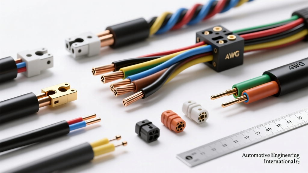
The Fallacy of Standard Ampacity Charts in Modern Vehicles
When technicians and engineers approach wire gauge sizing for automotive applications, the immediate instinct is to consult a standard American Wire Gauge (AWG) ampacity chart. However, these generic charts are fundamentally flawed for modern vehicle architectures. Standard reference tables typically assume a 12-volt system, a maximum ambient temperature of 75°C, and a single wire routed in free air. Today's automotive electrical landscape is dominated by 48-volt mild-hybrid Belt-Driven Starter Generators (BSG), 400-volt to 800-volt electric vehicle (EV) traction inverters, and high-density wiring harnesses routed through engine bays where ambient temperatures routinely exceed 125°C.
Advanced wire gauge sizing requires a multidimensional approach that accounts for insulation chemistry, voltage drop tolerances, thermal derating due to wire bundling, and the mechanical realities of terminal crimping. Selecting the wrong gauge in a high-current circuit does not merely result in a blown fuse; it initiates a cascade of thermal degradation that can lead to dielectric breakdown, terminal oxidation, and catastrophic harness fires. This guide provides a deep technical dive into the physics and SAE standards governing high-current automotive wire gauge sizing.
SAE J1128 vs. J2202: Insulation Chemistry and Thermal Limits
The ampacity of a copper conductor is ultimately limited not by the copper itself, but by the thermal threshold of its insulation. The Society of Automotive Engineers (SAE) defines strict classifications for low-tension and heavy-duty automotive cables. While older vehicles relied heavily on Polyvinyl Chloride (PVC) insulation, modern high-current wire gauge sizing mandates the use of Cross-Linked Polyethylene (XLPE) due to its superior thermal and chemical resistance.
Under SAE J1128 standards, XLPE-insulated wires are categorized by wall thickness and temperature tolerance. Thin-wall and special thin-wall designs allow for smaller overall cable diameters, reducing harness weight and stiffness without sacrificing current-carrying capacity. Below is a technical comparison of common automotive insulation types used in high-current applications:
| SAE Type | Insulation Material | Max Temp (°C) | Wall Thickness (in) | Primary Application |
|---|---|---|---|---|
| HDT | PVC | 90°C | 0.030 - 0.093 | Legacy 12V starter/alternator feeds |
| TXL | XLPE | 125°C | 0.016 - 0.045 | Standard cabin and chassis 12V routing |
| GXL | XLPE | 125°C | 0.012 - 0.035 | High-density engine bay harnesses |
| SXL | XLPE | 125°C | 0.020 - 0.055 | High-current 48V BSG and EV cooling pumps |
When performing wire gauge sizing for a 48V mild-hybrid system, engineers frequently select SXL or GXL wire. The cross-linking process creates a three-dimensional molecular bond that prevents the insulation from melting even if the copper core reaches 150°C during a transient short-circuit event. In contrast, PVC (HDT) will melt and flow away from the terminal crimp at sustained temperatures above 105°C, exposing bare copper to moisture and corrosive engine bay gases.
The Physics of Voltage Drop in 48V and High-Voltage EV Architectures
Ampacity (the ability of a wire to carry current without overheating) is only half of the wire gauge sizing equation. The second critical factor is voltage drop. In a standard 12V system, a 0.5V drop across a headlight circuit is negligible. However, in high-current, lower-voltage architectures like 48V mild-hybrids, voltage drop directly impacts system efficiency and ECU logic states.
Consider a 48V Belt-Driven Starter Generator (BSG) that requires a peak cranking current of 180 Amps. The power distribution module (PDM) is located in the trunk, requiring a 4-meter (13.12 ft) cable run to the BSG in the engine bay. Using the standard voltage drop formula for DC circuits:
VD = (2 x K x I x L) / CM
- K = Specific resistance of copper (12.9 ohms-cmil/ft at 75°C)
- I = Current (180A)
- L = One-way length in feet (13.12 ft)
- CM = Circular mils of the conductor
If we attempt to use 4 AWG wire (CM = 41,740), the calculation yields:
VD = (2 x 12.9 x 180 x 13.12) / 41,740 = 1.46 Volts.
While a 1.46V drop on a 48V system might seem acceptable (roughly 3%), this calculation assumes a baseline temperature of 75°C. Under-hood temperatures of 125°C increase the resistivity of copper (K rises to approximately 14.5). Furthermore, if the BSG control module requires a minimum of 46V to maintain closed-loop torque control during engine stop-start events, a 1.46V drop combined with internal contact resistance could trigger a low-voltage fault code (e.g., U0100 or P0A0F).
By upsizing to 2 AWG SXL wire (CM = 66,360), the voltage drop at elevated temperatures is reduced to approximately 1.05V, ensuring robust voltage delivery during peak transient loads. For high-voltage EV traction cables (400V+), voltage drop is less of a concern for ECU logic, but it directly translates to I²R heat generation, necessitating massive 1/0 AWG or 2/0 AWG aluminum or copper shielded cables.
Thermal Derating: Bundling and Ambient Heat Penalties
Automotive wiring harnesses are rarely routed as single, isolated conductors. They are bundled into corrugated looms, wrapped in Tesa tape, and secured to chassis rails. When multiple current-carrying conductors are bundled together, the inner wires cannot dissipate heat into the surrounding air. This trapped heat necessitates severe derating of the wire's baseline ampacity during the wire gauge sizing process.
According to TE Connectivity's automotive wiring design guidelines, bundling and ambient temperature act as multiplicative penalties against a wire's current-carrying capacity. The following derating matrix must be applied to baseline AWG ampacity charts:
| Wires in Bundle (Carrying >50% Load) | Ambient Temp (°C) | Derating Multiplier | Effective Ampacity (Baseline 150A for 4 AWG SXL) |
|---|---|---|---|
| 1 (Single Wire in Free Air) | 40°C | 1.00 | 150A |
| 2 to 4 Wires | 40°C | 0.80 | 120A |
| 5 to 7 Wires | 40°C | 0.70 | 105A |
| 1 (Single Wire) | 105°C (Near Exhaust) | 0.65 | 97.5A |
| 5 to 7 Wires | 105°C (Near Exhaust) | 0.45 | 67.5A |
As illustrated in the table, a 4 AWG SXL wire that is theoretically rated for 150A in free air at 40°C is effectively limited to just 67.5A if routed in a dense, 7-wire bundle near an exhaust manifold. In this scenario, proper wire gauge sizing dictates stepping up to 1 AWG or 1/0 AWG to safely carry the 150A load without exceeding the 125°C thermal limit of the XLPE insulation.
Aluminum vs. Copper: The Weight-Saving Compromise
To reduce vehicle mass and lower material costs, many OEMs are transitioning from copper to aluminum for heavy-gauge battery cables and alternator feeds. Aluminum has approximately 61% of the conductivity of copper by volume, and it is highly susceptible to galvanic corrosion and cold flow (creep) under mechanical pressure. When executing wire gauge sizing with aluminum, the general rule of thumb is to increase the wire size by two full AWG steps to match the ampacity and voltage drop characteristics of copper. For example, if a circuit requires 2 AWG copper, the equivalent aluminum conductor must be sized at 1/0 AWG. Furthermore, aluminum wire gauge sizing requires specialized bi-metallic (copper-aluminum) crimp terminals and the application of antioxidant joint compounds to prevent the formation of high-resistance aluminum oxide layers at the terminal interface.
Real-World Failure Modes from Incorrect Wire Gauge Sizing
Undersizing a wire in a high-current automotive circuit rarely results in an immediate, catastrophic failure. Instead, it initiates a slow, insidious degradation cycle. When a wire is undersized, it operates continuously near its thermal ceiling. This constant heat cycling causes the insulation to become brittle, leading to micro-cracking when the harness flexes during steering or suspension articulation.
More critically, the heat travels down the copper strands via thermal conduction directly into the terminal crimp barrel. Standard mechanical crimps rely on cold-welding the copper strands to the brass or tin-plated terminal. Sustained temperatures above 100°C accelerate galvanic corrosion between dissimilar metals, increasing the contact resistance at the crimp. This higher resistance generates even more localized heat (following Joule's first law), creating a thermal runaway loop that ultimately melts the connector housing and causes an open circuit or short to ground.
To mitigate this in high-current applications (such as 48V BSG feeds or EV battery cooling pumps), advanced wire gauge sizing must be paired with ultrasonic welding for terminal termination. Ultrasonic welding uses high-frequency acoustic vibrations to fuse the copper strands into a solid, monolithic block before crimping, eliminating the microscopic air gaps where oxidation typically begins. Additionally, when terminating heavy-gauge ring terminals to busbars or starter studs, strict adherence to torque specifications is mandatory. For example, an M8 terminal stud securing a 2 AWG battery cable requires exactly 20 Nm ± 2 Nm of torque. Under-torquing allows for micro-movements and arcing, while over-torquing yields the copper, reducing the cross-sectional area at the lug and creating a localized high-resistance hotspot.
Color Coding and Shielding in High-Current Architectures
Wire gauge sizing also intersects with harness identification and electromagnetic compatibility (EMC). In 48V mild-hybrid systems, SAE and ISO standards recommend distinct color coding to prevent technicians from accidentally cross-connecting 48V and 12V systems. While 12V systems universally utilize Red (RED) for power and Black (BLK) for ground, 48V architectures frequently employ Blue with a Green tracer (BLU/GRN) or solid Orange (ORG) for high-voltage lines. For high-current AC circuits, such as those feeding an EV HVAC compressor or electric power steering (EPS) motor, the wire gauge must account for the skin effect at higher frequencies, and the conductors must be wrapped in a braided copper shield. This shield must be properly terminated to a dedicated drain wire (typically 10 AWG or 12 AWG) and grounded to the chassis via a 360-degree shielded backshell to prevent high-frequency electromagnetic interference (EMI) from disrupting low-voltage CAN-FD and LIN bus communication networks.
Authoritative References and Further Reading
For engineers and master technicians designing or repairing advanced automotive electrical systems, relying on generic hardware store charts is unacceptable. The following resources provide the empirical data required for precise wire gauge sizing:
- SAE International J1128: Low Tension Primary Cable standards, detailing insulation thickness, thermal aging requirements, and scrape abrasion resistance for automotive wire.
- Mouser Electronics Automotive Wiring Guide: Comprehensive technical data on XLPE vs. PVC dielectric breakdown voltages and high-current terminal crimp specifications.
- TE Connectivity Automotive Harness Design: Application notes on thermal derating matrices, ultrasonic welding parameters, and high-voltage shielding methodologies.