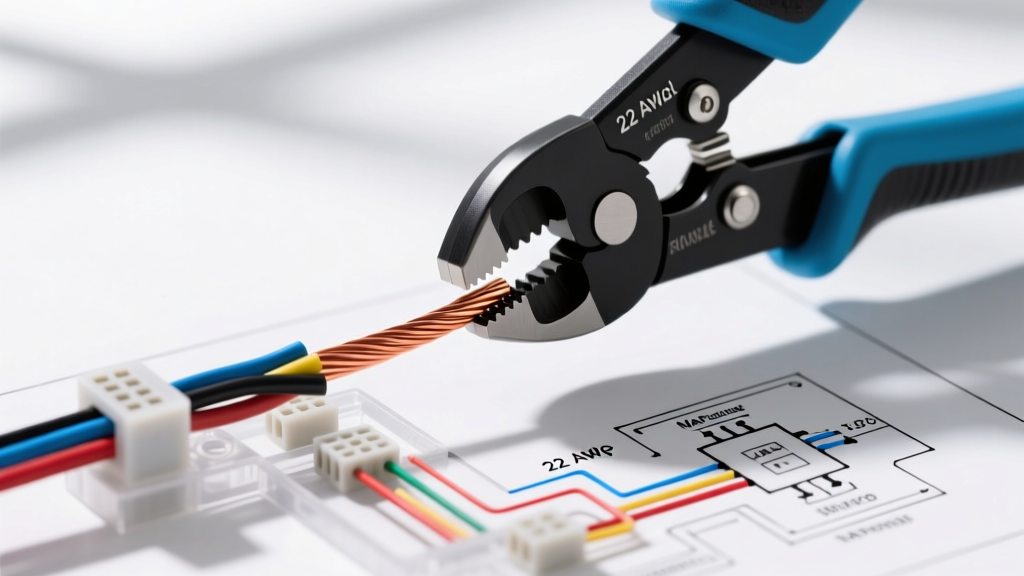
Understanding 22 AWG in Automotive Signal Circuits
When navigating modern automotive electrical systems, understanding the specific application of wire gauges is critical. While heavy 10 AWG or 8 AWG wires handle high-current loads like starter motors and cooling fans, 22 AWG (American Wire Gauge) wire is the backbone of low-current signal transmission. You will frequently encounter 22 gauge wire in 5-volt reference circuits, CAN bus networks, and analog sensor signal returns. Because these circuits carry minimal amperage (typically under 1A), the primary concern is not ampacity or thermal melting, but rather maintaining signal integrity, preventing voltage drop, and resisting high-frequency vibration.
In this comprehensive guide, we will walk through a complete wiring diagram for a standard 3-pin Manifold Absolute Pressure (MAP) sensor to contextualize the circuit. From there, we will provide a masterclass on how to crimp 22 gauge wire properly, ensuring your repairs meet OEM standards and prevent ghost electrical faults.
Complete Wiring Diagram Walkthrough: 3-Pin MAP Sensor
The MAP sensor is a critical engine management component that measures intake manifold vacuum/pressure and converts it into a voltage signal for the Powertrain Control Module (PCM). Most GM and Ford applications utilize a 3-pin Delphi (Aptiv) Metri-Pack 150 or Molex MX150 connector housing for this sensor. Let us break down the circuit architecture.
Pinout and Wire Color Specifications
Below is the standard pinout configuration for a typical GM LS-style MAP sensor harness. Note the specific use of 22 AWG for the sensitive logic circuits.
| Pin Cavity | Function | Standard Wire Color | Wire Gauge | Circuit Purpose |
|---|---|---|---|---|
| Pin A | 5V Reference | Gray | 22 AWG | Provides a stable 5.0V logic supply from the PCM to the sensor internal IC. |
| Pin B | MAP Signal | Yellow or Green | 22 AWG | Returns a variable voltage (0.5V - 4.5V) back to the PCM based on manifold pressure. |
| Pin C | Low Reference (Ground) | Black | 20 or 22 AWG | Dedicated sensor ground path back to the PCM to prevent ground-loop interference. |
Because Pin A and Pin B are 22 AWG signal wires, any increase in resistance at the connector terminal due to a poor crimp will act as a voltage divider. A mere 1.5 ohms of resistance from a botched crimp on the 5V reference wire can drop the voltage at the sensor to 4.2V, triggering a P0107 (MAP Sensor Circuit Low Voltage) diagnostic trouble code.
How to Crimp 22 Gauge Wire: Step-by-Step Execution
Crimping 22 gauge wire requires precision. The copper strand bundle is only 0.64mm in diameter, making it highly susceptible to being cut by improper tooling or crushed by excessive force. Follow this exact sequence to achieve a gas-tight, cold-welded connection.
Step 1: Tool and Terminal Selection
Never use non-ratcheting, generic crimping pliers for 22 AWG automotive wire. You must use a ratcheting crimper calibrated for 22-18 AWG (or 0.35mm² - 0.5mm² metric) terminals. For a MAP sensor repair, you will need:
- Terminal: Delphi Metri-Pack 150 Female Terminal (Part #12015797 or equivalent) designed for 22-18 AWG.
- Wire Seal: Green ribbed silicone seal (for 22-18 AWG). The seal must slide over the wire insulation to ensure weatherproofing.
- Crimper: A ratcheting die set specifically stamped for Metri-Pack 150 or standard open-barrel F-type terminals.
Step 2: Precision Stripping
Strip the 22 AWG GXL or TXL wire insulation to exactly 3.5mm to 4.0mm. If you strip too much, bare copper will sit outside the terminal, risking a short circuit against the connector housing. If you strip too little, the insulation will be caught inside the conductor crimp tabs, creating an open circuit. Use a high-quality automatic wire stripper calibrated for 22 AWG to avoid nicking the outer copper strands.
Step 3: The Crimping Sequence
- Thread the Seal: Slide the green silicone weather seal onto the wire before crimping. The wide end of the seal should face the stripped copper.
- Position the Terminal: Place the Metri-Pack terminal into the ratcheting crimper's 22 AWG die. Ensure the open barrel tabs are facing up and the seam of the terminal is centered.
- Conductor Crimp: Insert the bare copper strands into the front (smaller) barrel tabs. Squeeze the crimper one click to hold the terminal. Verify that the copper strands are fully seated and no insulation is trapped in the front tabs.
- Insulation Crimp: Slide the wire forward so the jacket rests in the rear (larger) barrel tabs. Complete the ratchet cycle. The rear tabs should fold over and grip the wire insulation tightly without piercing or cutting the GXL jacket.
- Seat the Seal: Push the silicone seal forward until it butts flush against the rear of the terminal's insulation crimp.
Step 4: Visual Inspection Criteria
According to SAE J1128 and IPC-A-620 automotive wiring standards, a perfect 22 AWG crimp must exhibit the following:
- Front Bellmouth: A slight flare of the terminal metal just in front of the conductor crimp (approx. 0.2mm) to prevent the sharp edge from shearing the copper strands during vibration.
- Conductor Brush: The tips of the 22 AWG copper strands should be barely visible (0.5mm) extending past the front of the conductor crimp barrel.
- Insulation Crimp: The rear tabs must form a complete 'O' or overlapping shape around the wire jacket, providing strain relief.
22 Gauge Wire Technical Specifications Chart
When designing or repairing harnesses, reference these baseline specifications for standard 22 AWG stranded copper wire (GXL/TXL insulation types commonly used in engine bays).
| Specification | Imperial (AWG) | Metric Equivalent |
|---|---|---|
| Nominal Diameter | 0.0253 inches (0.643 mm) | 0.64 mm |
| Cross-Sectional Area | 0.000503 sq inches | 0.326 mm² (Often grouped as 0.35mm²) |
| Resistance @ 20°C | 16.14 Ohms / 1,000 ft | 52.9 Ohms / 1,000 m |
| Max Ampacity (Chassis) | 7.0 Amps | 7.0 Amps |
| Max Ampacity (Signal/PCM) | 1.0 - 2.0 Amps | 1.0 - 2.0 Amps |
| Pull-Test Minimum (Crimp) | 15 lbs (66.7 N) | 66.7 Newtons |
Note: While 22 AWG can technically handle 7 amps in free air chassis wiring, automotive PCMs limit 5V reference and signal circuits to milliamp ranges. The physical strength of the crimp joint is far more critical than the thermal ampacity in these applications.
Common Failure Modes and Troubleshooting 22 AWG Crimps
Even when you know how to crimp 22 gauge wire, environmental factors and tool wear can cause failures. Use this diagnostic tree to identify 22 AWG crimp-related faults in sensor circuits.
Symptom: Intermittent Sensor Dropouts (e.g., Stalling, Hesitation)
- Cause 1: 'Birdcaging' of Strands. If the wire stripper nicked the outer copper strands, they will splay outward (birdcage) when pushed into the terminal. These strands bypass the crimp barrel, reducing the contact area by up to 40%. Fix: Cut back, re-strip with calibrated tools, and re-crimp.
- Cause 2: Missing Wire Seal. Without the silicone ribbed seal, moisture wicks into the terminal via capillary action, causing galvanic corrosion between the copper wire and the tin-plated brass terminal. Fix: Always use the correct color-coded seal for the gauge size.
Symptom: P0106 / P0107 MAP Sensor Codes
- Cause: Insulation Trapped in Conductor Crimp. If the wire was not stripped far enough, the GXL insulation gets folded into the front copper crimp tabs. Copper oxide and plastic act as an insulator, creating a high-resistance joint. The PCM sees a voltage drop on the 5V reference line and assumes the sensor has failed. Fix: Perform a voltage drop test across the crimped connection under load. A good 22 AWG crimp should show less than 0.01V drop.
Authoritative References and Further Reading
For deeper engineering standards regarding automotive wire gauges, terminal retention forces, and insulation materials, consult the following resources:
- SAE J1128: Low Tension Primary Cable Standard - The definitive Society of Automotive Engineers standard covering GXL, TXL, and SXL wire insulation requirements and physical dimensions.
- Molex MX150 Sealed Connector System Specifications - Detailed application tooling specs, crimp pull-force requirements, and wire gauge mapping for modern sealed automotive signal connectors.
- Standard AWG to Metric Wire Size Conversion Chart - A comprehensive engineering reference for calculating voltage drop, resistance per foot, and cross-sectional area across all standard American Wire Gauges.
Mastering how to crimp 22 gauge wire is a foundational skill for any automotive electrician or DIY enthusiast. By respecting the physical limitations of the wire, utilizing ratcheting tooling, and adhering to strict visual inspection criteria, you ensure that critical engine management sensors receive clean, uninterrupted logic signals.