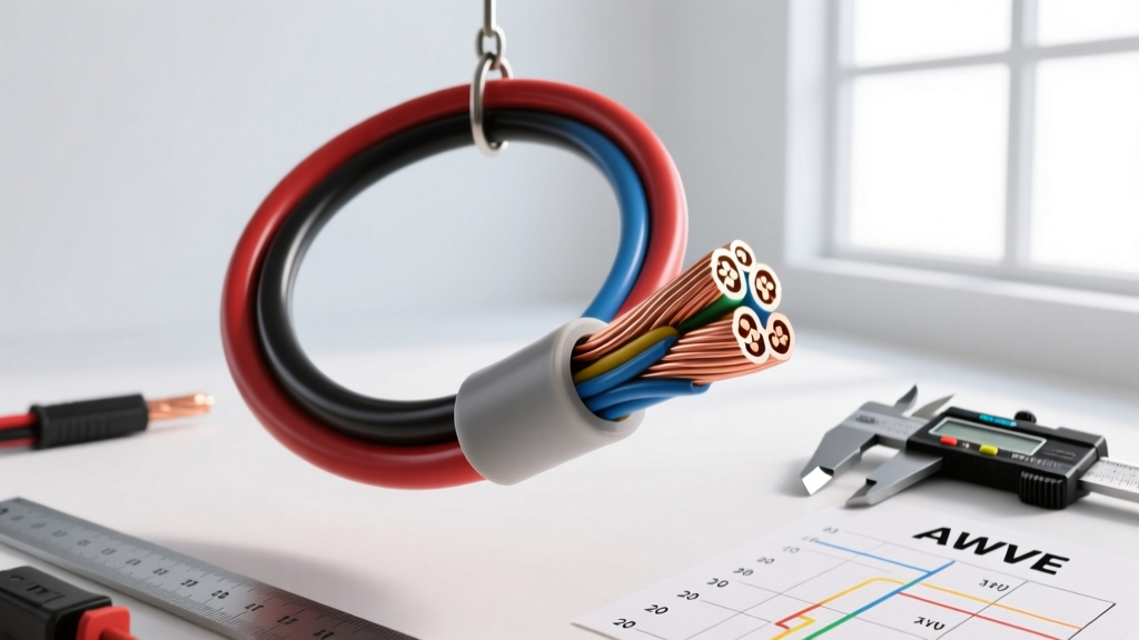
Introduction to AWG 20 in Automotive Electrical Systems
In the realm of automotive electrical engineering, 20 gauge wire (AWG 20) serves as the critical backbone for low-current signaling, sensor networks, and multiplexed communication buses. While heavier gauges like 10 AWG or 4 AWG handle the high-amperage demands of starters, alternators, and EV traction inverters, 20 AWG is the unsung hero of the Engine Control Unit (ECU) and Transmission Control Module (TCM). Understanding the precise metallurgical, electrical, and physical properties of 20 gauge wire is essential for diagnosing complex drivability issues, designing custom harnesses, and ensuring long-term reliability in harsh under-hood environments.
This advanced technical deep dive explores the exact specifications of 20 AWG wire, its ampacity limits under SAE J1128 standards, voltage drop calculations, and the specific terminal crimping methodologies required to prevent micro-fretting and galvanic corrosion in modern vehicle networks.
Core Specifications: Ampacity, Resistance, and Physical Dimensions
The American Wire Gauge (AWG) system dictates that as the gauge number increases, the physical diameter and cross-sectional area of the wire decrease. AWG 20 sits squarely in the 'signal and low-power' category. It is crucial to note that automotive wire is typically stranded (usually 19 to 41 individual copper strands) to withstand the constant vibration and thermal cycling inherent in vehicle operation, unlike solid-core wire used in residential construction.
| Property | AWG 20 Specification | Metric Equivalent |
|---|---|---|
| Nominal Diameter | 0.0320 inches | 0.812 mm |
| Cross-Sectional Area | 0.000802 sq inches | 0.518 mm² |
| Resistance (Copper @ 20°C) | 10.15 Ohms / 1,000 ft | 33.3 Ohms / km |
| Max Ampacity (Chassis Wiring) | 3.0 Amps | SAE J1128 / ISO 6722 |
| Max Ampacity (Power Transmission) | 1.5 Amps | Conservative bundled rating |
Note: Ampacity ratings for 20 gauge wire vary significantly based on insulation type (PVC vs. XLPE), ambient temperature, and whether the wire is routed in free air or bundled tightly inside a harness conduit. High-temperature Cross-Linked Polyethylene (XLPE) insulation rated for 125°C allows for slightly higher current densities than standard 105°C PVC.
Automotive Applications: Where 20 AWG Excels
ECU Sensors and Low-Current Signal Lines
Modern engine management systems rely on 5-volt reference circuits to read analog sensors. Throttle Position Sensors (TPS), Manifold Absolute Pressure (MAP) sensors, and narrowband Oxygen (O2) sensors typically utilize 20 AWG wire for their signal and ground return paths. Because the ECU's internal pull-up resistors limit current draw to mere milliamps (usually under 50mA), the low ampacity of 20 gauge wire is perfectly adequate. However, the 10.15 ohms per 1,000 feet resistance becomes a critical factor in voltage drop calculations over long harness runs, particularly in heavy-duty trucks and RVs.
CAN Bus Networks and Multiplexing
The Controller Area Network (CAN bus) is the central nervous system of modern vehicles, allowing modules to communicate via differential signaling. The physical layer of a standard high-speed CAN bus (ISO 11898-2) heavily relies on 20 gauge twisted-pair wiring. The twisting of the two 20 AWG wires (typically Green/White for CAN-High and Purple/White for CAN-Low) cancels out electromagnetic interference (EMI) from ignition coils and alternators. The standard 120-ohm terminating resistors at each end of the bus are calibrated specifically around the impedance characteristics of 20 AWG twisted pairs.
Wideband O2 Sensor Heater Circuits (A Warning)
While 20 AWG is ideal for sensor signals, it is a common point of failure when misapplied. Wideband O2 sensors require internal heating elements to reach operating temperature (over 1,400°F). These heaters can draw 2 to 4 amps initially. Using 20 gauge wire for a wideband heater circuit will result in severe voltage drop, excessive wire heating, and eventual insulation meltdown. Heater circuits require a minimum of 16 AWG or 14 AWG wire, reserving the 20 AWG strictly for the Nernst cell signal and calibration lines.
Voltage Drop Calculations for 20 Gauge Wire
Voltage drop is the enemy of precision sensor readings. If an ECU sends a 5.00V reference signal to a MAP sensor, and the 20 AWG ground return wire has excessive resistance, the ECU will read a skewed voltage, potentially triggering false diagnostic trouble codes (DTCs) like P0107 (MAP Circuit Low Voltage). The formula for voltage drop is V = I × R, where R is the total resistance of the complete circuit loop (positive wire + ground wire).
| Current Draw | 5 ft Loop (10 ft total wire) | 10 ft Loop (20 ft total wire) | 20 ft Loop (40 ft total wire) |
|---|---|---|---|
| 0.1A (Typical Sensor) | 0.010 V | 0.020 V | 0.041 V |
| 0.5A (Solenoid/Relay) | 0.051 V | 0.102 V | 0.203 V |
| 1.5A (Max Chassis Limit) | 0.152 V | 0.305 V | 0.609 V |
As demonstrated, pushing 1.5 amps through a 40-foot total loop of 20 gauge wire results in a 0.609V drop. In a 12V system, this is a 5% drop, which is generally acceptable for lighting but unacceptable for precision 5V logic circuits or 12V PWM (Pulse Width Modulation) solenoids.
Terminal Crimping and Connector Selection for AWG 20
The reliability of a 20 AWG wire is entirely dependent on the terminal crimp. A poorly executed crimp introduces micro-gaps that lead to oxidation, increased resistance, and eventual thermal failure. Automotive environments demand gas-tight crimps that prevent moisture and oxygen from reaching the copper strands.
- Deutsch DT Series: The industry standard for heavy-duty and motorsport applications. TE Connectivity Deutsch DT connectors utilize Size 20 pins, which are rated for 7.5 amps but are designed to accept wire ranges from 0.32 mm² to 0.82 mm² (AWG 22 to 18). The solid stainless steel retention tangs ensure the pin locks securely into the housing cavity.
- TE Superseal 1.5 Series: Commonly used in European and Asian OEM engine harnesses. The 0.64mm tab width is optimized for 20 AWG wire, featuring a secondary locking mechanism (TPA) to prevent terminal back-out during high-vibration events.
- Molex MX150: A high-performance, sealed connector system that reduces packaging size. The MX150 terminal for 0.35-0.50 mm² wire provides an exceptional gas-tight F-crimp profile specifically engineered for 20 AWG stranded copper.
Crimping Best Practice: Always use a ratcheting crimp tool calibrated for the specific terminal profile. For open-barrel terminals, the wire strands should be visible at the front of the conductor crimp wings, and the insulation crimp should securely grip the wire jacket without piercing it. A proper tear-drop or hexagonal crimp profile ensures maximum surface area contact.
Troubleshooting Common 20 AWG Failures
When diagnosing electrical faults, technicians often overlook the wire gauge itself, focusing instead on the sensors or the ECU. Here are real-world failure modes specific to 20 gauge automotive wiring:
1. Galvanic Corrosion at the Crimp Joint
If a copper 20 AWG wire is crimped into a nickel-plated or tin-plated terminal and exposed to moisture (common in wheel speed sensor harnesses), galvanic corrosion occurs. The dissimilar metals create a weak battery effect, generating copper oxide. This oxide is a semiconductor; it allows high-current testing with a multimeter to pass, but it severely restricts the high-frequency data signals on a CAN bus, leading to intermittent U-codes (Network Communication Faults).
2. Micro-Fretting in Connector Cavities
Micro-fretting occurs when engine vibration causes microscopic movement between the male and female terminals. In 20 AWG circuits carrying low voltage (like a 0-5V TPS signal), this movement generates frictional oxidation that spikes resistance. Using dielectric grease is a double-edged sword; while it keeps moisture out, thick grease can displace the contact pressure of small AWG 20 pins. Always use a specialized, low-viscosity electrical contact lubricant designed for low-current signal pins.
3. Wire Harness Chafing and Insulation Breakdown
Standard PVC-insulated 20 AWG wire becomes brittle over time due to under-hood heat cycling. If the harness rubs against an aluminum intake manifold or bracket, the insulation wears through. Because 20 AWG is often used for 12V injector drivers or 5V references, a short to ground can instantly fry the internal driver transistor inside the ECU. Upgrading to Raychem Spec 55 (Tefzel) or XLPE insulated 20 AWG wire in high-wear areas prevents catastrophic module failure.
Summary Reference for Harness Builders
When designing custom automotive harnesses, reserve 20 gauge wire strictly for: CAN bus pairs, 5V analog sensor signals, digital hall-effect sensor outputs (like crankshaft position sensors), and low-current ground returns. Never use 20 AWG for fuel injectors, ignition coils, wideband O2 heaters, or high-amperage solenoid grounds. By respecting the physical limits and resistance characteristics of AWG 20, you ensure signal integrity, eliminate ghost electrical faults, and build harnesses that withstand the brutal realities of the automotive environment.