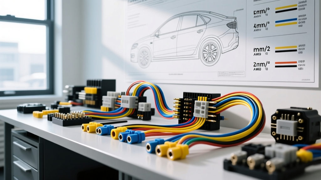
The Hidden Danger of Mixing AWG and Metric Wire
When repairing, modifying, or completely rebuilding an automotive wiring harness, one of the most catastrophic errors a technician can make is confusing American Wire Gauge (AWG) with Metric cross-sectional area (mm²). Modern global vehicles rely heavily on metric wiring standards, while older domestic vehicles and many aftermarket accessories use AWG. Without a precise wire gauge to millimeter conversion chart at your workbench, you risk severe voltage drops, melted insulation, ECU damage, and outright electrical fires.
The core issue stems from how these two systems measure wire. AWG is based on the number of drawing dies used to reduce the wire's diameter (a lower AWG number means a thicker wire). Metric wire is measured by its total cross-sectional area in square millimeters (mm²). Because they measure fundamentally different physical properties, a direct 1:1 numerical translation does not exist. Assuming that '4 AWG' and '4 mm²' are interchangeable is a beginner mistake that routinely destroys vehicle electrical systems.
Essential Wire Gauge to Millimeter Conversion Chart
Below is the definitive wire gauge to millimeter conversion chart for automotive primary wire. This chart correlates AWG sizes to their closest metric equivalents, including cross-sectional area, approximate conductor diameter, and maximum chassis ampacity based on SAE J1128 and ISO 6722-1 standards for single-core cables at 105°C ambient engine bay temperatures.
| AWG Size | Metric Equivalent (mm²) | Conductor Area (mm²) | Approx. Diameter (mm) | Max Ampacity (Chassis) |
|---|---|---|---|---|
| 18 AWG | 0.8 mm² | 0.82 | 1.02 | 16A |
| 16 AWG | 1.0 mm² / 1.5 mm² | 1.31 | 1.29 | 22A |
| 14 AWG | 2.0 mm² | 2.08 | 1.63 | 32A |
| 12 AWG | 3.0 mm² | 3.31 | 2.05 | 41A |
| 10 AWG | 5.0 mm² | 5.26 | 2.59 | 55A |
| 8 AWG | 8.0 mm² | 8.37 | 3.26 | 73A |
| 6 AWG | 10.0 mm² / 13.0 mm² | 13.30 | 4.11 | 101A |
| 4 AWG | 20.0 mm² / 25.0 mm² | 21.15 | 5.19 | 135A |
| 2 AWG | 35.0 mm² | 33.62 | 6.54 | 170A |
| 1/0 AWG | 50.0 mm² | 53.49 | 8.25 | 245A |
Top 4 Catastrophic Mistakes When Converting Gauges
Mistake 1: Confusing Diameter (mm) with Cross-Sectional Area (mm²)
Many aftermarket wires are sold by their outer diameter or conductor diameter in millimeters, not their cross-sectional area. If you measure a wire's conductor with digital calipers and find it is exactly 2.0 mm in diameter, it is not 2.0 mm² wire. Using the formula for the area of a circle (A = π × r²), a 2.0 mm diameter wire has a radius of 1.0 mm. Therefore, the area is 3.14 mm², which is actually closer to 12 AWG. If you use this wire in a circuit designed for true 2.0 mm² (14 AWG) wire, you are fine. But if you assume a 2.0 mm diameter wire is equivalent to 10 AWG (5.0 mm²), you will overload the circuit, causing the insulation to melt and potentially shorting against the chassis.
Mistake 2: The '4mm² is 4 AWG' Fallacy
This is the most dangerous numerical coincidence in automotive wiring. A technician upgrading an alternator might purchase '4mm' wire at a local auto parts store, assuming it is equivalent to 4 AWG battery cable. In reality, true 4 AWG wire has a cross-sectional area of 21.15 mm². A 4.0 mm² wire is equivalent to roughly 11 AWG. If you connect a 150-amp alternator to a 4.0 mm² wire (rated for roughly 32 amps in chassis wiring), the wire will act as a massive resistor. It will generate extreme heat, melt the bulkhead connector, and trigger a P0562 (System Voltage Low) code at the PCM before potentially catching fire.
Mistake 3: Ignoring Stranding Differences (SAE vs ISO)
The wire gauge to millimeter conversion chart only accounts for total copper area, not stranding flexibility. SAE J1128 and ISO 6722-1 dictate different stranding classes. Metric automotive wire often uses Class C or Class D fine stranding for high-flexibility applications (like door hinge boots or steering column clocksprings). Standard AWG wire typically uses coarser stranding. If you use standard coarse-strand AWG wire to repair a broken CAN-bus line inside a driver's door jamb, the stiff wire will work-harden and snap from repeated door open/close cycles, causing intermittent U0140 (Lost Communication With Body Control Module) codes that are a nightmare to diagnose.
Mistake 4: Miscalculating Voltage Drop on Long CAN-Bus Runs
High-speed CAN-bus networks (like GM's GMLAN or Ford's MS-CAN) typically use 0.35 mm² or 0.50 mm² wire (roughly 22 AWG to 20 AWG). Because these wires are so thin, voltage drop over long distances (such as running from the front ECU to a rear trailer module) can corrupt data packets. When converting from metric to AWG for these repairs, technicians often round up to 18 AWG (0.82 mm²) thinking 'bigger is better.' However, 18 AWG wire is too thick to properly seat into the micro-timer or Deutsch DT 20-way ECU connector cavities. Forcing an 18 AWG wire into a 0.35 mm² pin cavity bends the terminal tangs, resulting in a loose pin connection that causes intermittent network drops.
Real-World Troubleshooting: Melted Alternator Harness Case Study
Vehicle: 2014 Ford F-150 5.0L V8
Symptom: Battery warning light illuminated, voltage dropping to 11.4V at idle, burning smell from the engine bay.
The Mistake: The previous owner replaced the factory 175A alternator with a 220A aftermarket unit. They extended the factory alternator charge wire using what they believed was '4 AWG' wire purchased from a generic online marketplace. The wire was actually labeled '4mm²' (approx. 11 AWG).
The Failure: The 4mm² wire could not handle the 180A continuous load required by the truck's electric power steering and aftermarket lighting. The wire's insulation melted inside the corrugated loom, fusing to the A/C compressor clutch coil wiring. This caused a dead short, blowing the 200A mega fuse in the Battery Junction Box (BJB) and frying the PCM's internal voltage regulator driver due to a voltage spike during the short-circuit event.
The Fix: We removed the melted harness section. Using the wire gauge to millimeter conversion chart, we selected true SAE J1128 compliant 2/0 AWG (approx. 67.4 mm²) marine-grade tinned copper wire to handle the 220A load safely. We terminated it with a 3/8-inch copper ring terminal, crimped using a hex-die hydraulic crimper, and applied a 15 Nm torque spec to the alternator B+ post.
Best Practices for Splicing Metric and AWG Harnesses
When you must transition between metric wire and AWG wire during a repair, never use twist-and-solder methods or cheap vinyl electrical tape. Follow this professional protocol:
- Match the Pin, Not Just the Wire: Always select the wire gauge that matches the terminal crimp barrel of the connector. If you are repinning a Bosch Junior Timer connector designed for 1.5 mm² wire, use exactly 1.5 mm² (16 AWG) wire. Do not force 14 AWG into the crimp.
- Use Adhesive-Lined Heat Shrink: When butt-splicing AWG to Metric, use a stepped heat-shrink butt connector (e.g., red-to-blue step-down). The internal polyamide adhesive melts and seals the joint against moisture and galvanic corrosion, which is critical in engine bay environments.
- Verify Stranding Class: For engine bay wiring (Class A or B, 105°C), standard AWG is fine. For high-vibration areas or cabin interiors, ensure you are using ISO 6722 Class C or D fine-strand metric wire to prevent fatigue failures.
- Color Code Compliance: Maintain OEM color codes where possible. For example, if repairing a GM LS engine alternator harness, the main charge wire should be Red (typically 8 AWG / 8.0 mm²), and the L-terminal ignition wire should be Brown (18 AWG / 0.8 mm²).
By strictly adhering to a verified wire gauge to millimeter conversion chart and understanding the physical differences between AWG and metric standards, you ensure the longevity, safety, and reliability of your vehicle's electrical architecture.