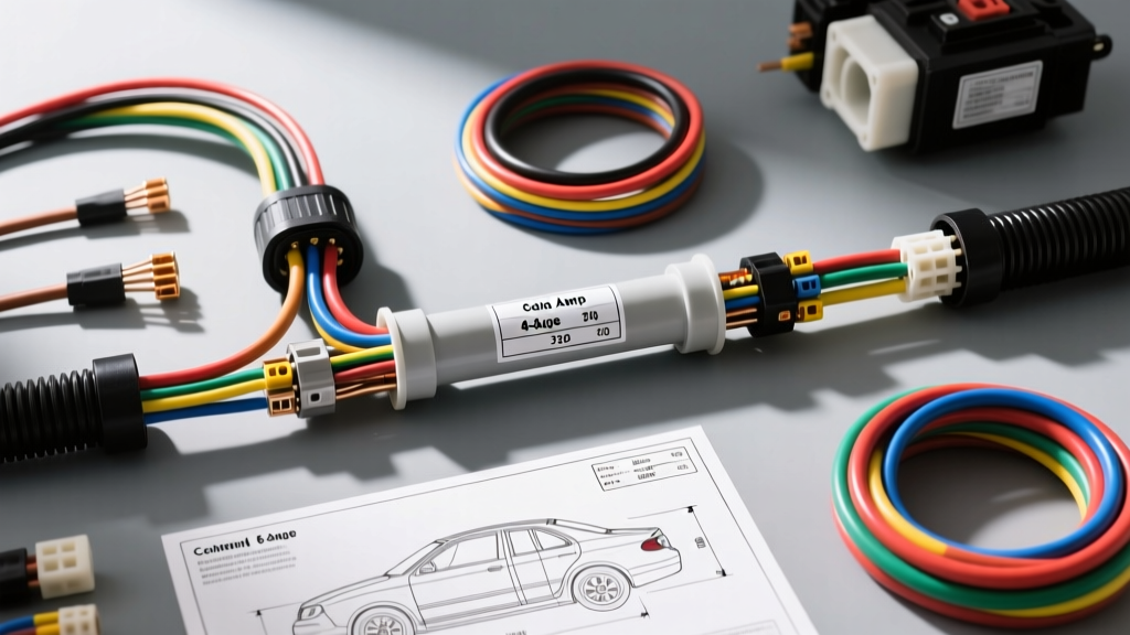
High-Current Dual-Battery Wiring Diagram Overview
When engineering a high-amperage electrical system for overland vehicles, marine applications, or EV conversions, proper cable management is just as critical as the electrical connections themselves. A common scenario in heavy-duty 4x4 builds (such as the Mercedes Sprinter or Toyota Land Cruiser) involves routing main charging cables alongside high-current control wires through the vehicle chassis. This brings up a frequent and critical installation question: what size conduit for 4 6 gauge wires is required to maintain safety, prevent chafing, and comply with fill-capacity standards?
In this complete wiring diagram walkthrough, we will trace a 220-amp alternator dual-battery system utilizing a Voltage Sensitive Relay (VSR). We will break down the exact circuit paths, calculate the required conduit dimensions based on SAE J1128 wire specifications, and provide actionable routing advice for automotive electrical experts.
Circuit Trace and Pin Configurations
The following walkthrough details a high-output charging system paired with a lithium house battery bank. The system relies on 4 AWG GXL wire for main power delivery and 6 AWG GXL wire for high-current relay triggering and Battery Management System (BMS) communication.
- Path 1 (Main Charge): Alternator B+ Terminal (M8 stud) → 4 AWG Red GXL → 150A MEGA Fuse → VSR Input Stud.
- Path 2 (House Feed): VSR Output Stud → 4 AWG Red GXL → House Battery B+ Busbar.
- Path 3 (Ignition Trigger): Ignition Switch (Pin 4, 12V Switched) → 6 AWG Blue GXL → VSR Coil Trigger (Pin 86).
- Path 4 (BMS Sense & Ground): VSR Coil Ground (Pin 85) → 6 AWG Black GXL → Chassis Ground Point G104.
Because Paths 1 and 3 (one 4 AWG and one 6 AWG) must cross the firewall and run parallel along the frame rail, they are bundled together. To protect against abrasion, moisture, and road debris, they must be housed in a protective conduit.
Answering the Core Question: What Size Conduit for 4 6 Gauge Wires?
To determine the correct conduit size, we cannot simply guess based on nominal wire gauge numbers. We must calculate the cross-sectional area of the specific wire insulation type and apply standard conduit fill rules. While automotive applications do not strictly fall under the National Electrical Code (NEC), professional installers adapt NEC Article 300.17 fill capacity rules to ensure heat dissipation and prevent wire jamming during installation.
Wire Outer Diameter (OD) and Cross-Sectional Area
Automotive wire is typically manufactured to SAE J1128 standards. GXL (Cross-linked, thin-wall) wire is the industry standard for high-temperature engine bay and chassis routing due to its reduced outer diameter compared to standard PVC wire.
- 4 AWG GXL Wire: Nominal OD = 0.265 inches. Cross-sectional area = π × (0.1325)² = 0.0551 sq in.
- 6 AWG GXL Wire: Nominal OD = 0.215 inches. Cross-sectional area = π × (0.1075)² = 0.0363 sq in.
If our conduit run includes two 4 AWG cables (Main Charge and Main Ground) and two 6 AWG cables (Trigger and BMS Sense), the total cross-sectional area of the wire bundle is:
(2 × 0.0551) + (2 × 0.0363) = 0.1102 + 0.0726 = 0.1828 sq in.
Conduit Fill Capacity Calculations
According to standard fill capacity guidelines for three or more wires in a single conduit, the maximum allowable fill is 40% of the conduit's internal cross-sectional area. This 60% void space is mandatory for heat dissipation and to allow the wires to bend without binding or damaging the insulation.
Required Internal Area = 0.1828 sq in. / 0.40 = 0.457 sq in.
Let us evaluate standard automotive and industrial conduit options:
- 1/2-inch Schedule 40 PVC: Internal area is approximately 0.285 sq in. (Fails the 40% fill rule; wires will jam and overheat).
- 3/4-inch Schedule 40 PVC: Internal area is approximately 0.533 sq in. (Passes the 40% fill rule; provides adequate room for heat dissipation).
- 1-inch Corrugated Split Loom: Nominal internal area varies due to the corrugated peaks and valleys, but effectively provides ~0.65 sq in. of usable space. (Highly recommended for flexible chassis routing).
The Verdict: When asking what size conduit for 4 6 gauge wires in a 4-wire bundle, the absolute minimum for rigid pass-throughs is 3/4-inch rigid conduit. For flexible chassis routing, use 1-inch corrugated split loom to account for the reduced effective area caused by the corrugation ridges.
Technical Specifications and Sizing Chart
| Wire Gauge (AWG) | Insulation Type | Outer Diameter (in) | Cross-Sectional Area (sq in) | Max Ampacity (Engine Bay) |
|---|---|---|---|---|
| 4 AWG | GXL (SAE J1128) | 0.265 | 0.0551 | 120A @ 125°C |
| 6 AWG | GXL (SAE J1128) | 0.215 | 0.0363 | 80A @ 125°C |
| 4 AWG | THHN (Building Wire) | 0.332 | 0.0865 | N/A (Not for auto) |
Note: Never use THHN building wire in automotive chassis applications. The nylon outer jacket becomes brittle when exposed to automotive fluids, UV light, and constant vibration, leading to catastrophic short circuits.
Chassis Routing, Grommets, and Firewalls
Routing a 3/4-inch rigid conduit or 1-inch corrugated loom through a vehicle firewall requires precision. When drilling the firewall for a 4-wire bundle of 4 and 6 AWG cables, you must account for the outer diameter of the protective grommet.
- Hole Sizing: Drill a 1-1/4 inch hole in the chassis sheet metal. This allows for the insertion of a heavy-duty EPDM rubber firewall bulkhead grommet.
- Sealing: Apply marine-grade silicone sealant around the outer edge of the grommet to prevent exhaust fumes and water from entering the cabin.
- Conduit Termination: The conduit should terminate exactly at the base of the grommet. Do not run corrugated loom through the grommet itself, as the sharp edges of the loom can cut into the rubber over time due to engine vibration.
- Clamping: Secure the conduit every 12 to 18 inches using UV-resistant nylon P-clips or aluminum Adel clamps lined with rubber. Never use zip-ties to secure conduit directly to sharp chassis edges.
Termination and Crimping Standards
Proper conduit sizing means nothing if the terminations fail. High-current 4 AWG and 6 AWG wires require specialized crimping techniques to ensure low resistance and high pull-out strength.
- Terminals: Use only oxygen-free copper, closed-barrel ring terminals. For 4 AWG, use M8 or 5/16" ring terminals depending on the busbar stud size. For 6 AWG, M6 or 1/4" terminals are standard.
- Crimping Tool: A standard hex-crimp die is acceptable, but a custom indent die or a hydraulic crimping tool calibrated to ABYC E-11 standards is preferred for high-vibration environments.
- Heat Shrink: Seal every termination with dual-wall, adhesive-lined heat shrink. The inner meltable adhesive layer creates a watertight seal that prevents capillary action from drawing moisture into the copper strands, which causes green verdigris corrosion and high-resistance voltage drops.
Common Failure Modes and Troubleshooting
Even with correct conduit sizing, high-amperage automotive circuits are prone to specific failure modes. Use this diagnostic matrix to troubleshoot common issues in 4/6 AWG harnesses.
Symptom: VSR Chatters or Fails to Engage
- Cause: Voltage drop on the 6 AWG ignition trigger wire (Path 3).
- Fix: Check for loose crimps at the ignition switch Pin 4. A poor crimp on 6 AWG wire will drop the 12V signal below the VSR's 11.5V engagement threshold under load.
Symptom: Melted Conduit or Discolored Wire Insulation
- Cause: Exceeding the 40% conduit fill rule, trapping heat, or using undersized wire for the continuous load.
- Fix: Verify the alternator output. If a 220A alternator is pushing 180A continuously through a single 4 AWG wire, the wire will overheat regardless of conduit size. Upgrade to dual parallel 4 AWG runs or a single 2/0 AWG cable for the main charge path.
Symptom: Intermittent BMS Fault Codes
- Cause: Chafing of the 6 AWG BMS sense wire inside a corrugated loom that was improperly sized (e.g., forced into a 1/2" loom instead of 1").
- Fix: Inspect the entire length of the 6 AWG wire where it passes through tight chassis bends. Replace any wire with compromised GXL insulation and upgrade to a 1-inch loom to provide adequate clearance.