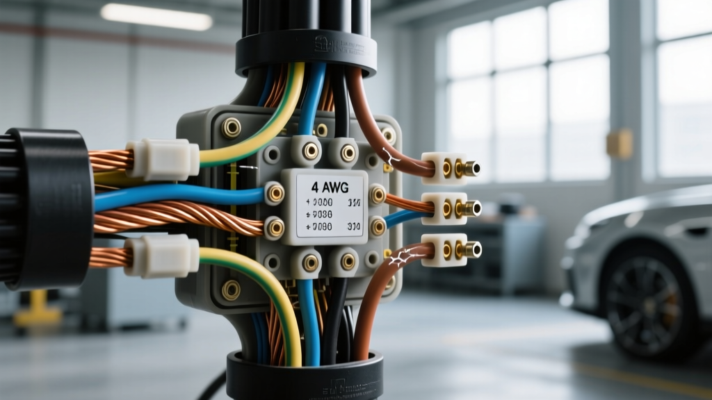
The 'Bigger is Better' Fallacy in Automotive Wiring
When building custom harnesses or repairing vehicle electrical systems, a common misconception among novice technicians is that upsizing wire gauge universally improves safety and performance. The logic seems sound: a thicker wire has lower resistance, handles more amperage, and reduces voltage drop over long runs. However, when engineering a reliable automotive electrical architecture, asking what happens if wire gauge is too big reveals severe mechanical, thermal, and signal integrity vulnerabilities. Modern vehicles rely on precision-matched components, from the cross-sectional area of the copper strands to the specific dielectric properties of the insulation. Forcing an oversized wire into a system designed for a smaller gauge introduces critical failure points that can lead to intermittent electrical faults, data bus corruption, and even localized thermal events.
This advanced technical deep dive explores the metallurgical, mechanical, and electrical consequences of using oversized wire in automotive applications, referencing SAE J1128 Standard for Low Tension Primary Cable and OEM connector specifications to illustrate why precision matching is non-negotiable.
Mechanical Failure: Crimp Compression and Terminal Mismatch
The most immediate and catastrophic failure mode when using oversized wire occurs at the termination point. Automotive terminals—whether they are stamped open-barrel contacts in a Molex MX150 connector or closed-barrel pins in a Deutsch DT series—are engineered with precise crimp geometries. These geometries are calculated based on the specific cross-sectional area of the copper conductor and the outer diameter of the wire insulation.
Wire Barrel Deformation and Strand Shaving
If you attempt to crimp a 12 AWG TXL (Thin Wall) wire into a terminal designed for 16 AWG, the wire barrel will not close properly. The crimp wings will bottom out against the terminal base before achieving the necessary compression ratio on the copper strands. To force the wire into the cavity, some builders resort to 'strand shaving'—stripping away outer copper strands to reduce the wire's diameter. This practice is a cardinal sin in automotive wiring. It artificially creates a high-resistance bottleneck at the exact point where mechanical stress and electrical load are highest, directly violating the pull-out force requirements mandated by SAE standards.
Insulation Barrel and Strain Relief Compromise
Beyond the conductor crimp, the insulation barrel is designed to grip the specific outer diameter of the wire's jacket (e.g., GXL, SXL, or TXL). If the wire gauge is too large, the insulation barrel cannot wrap securely around the jacket. This eliminates the strain relief mechanism, meaning any physical tug on the harness transfers the entire mechanical load directly to the copper crimp. Over time, engine vibration and chassis flex will cause the copper strands to fatigue and snap inside the terminal housing, resulting in an open circuit that is notoriously difficult to diagnose with a standard multimeter.
Thermal Runaway at the Junction Point
While a larger wire gauge reduces resistance along the length of the cable run, it inadvertently shifts the thermal vulnerability to the terminal junction. According to Joule's First Law, heat generation is proportional to the square of the current multiplied by the resistance ($I^2R$). When an oversized wire is improperly crimped or forced into an undersized terminal cavity, the micro-voids between the copper strands and the terminal metal increase the contact resistance at that specific node.
Under heavy continuous loads—such as a 40A cooling fan circuit or a high-amperage fuel pump—the wire itself will remain cool due to its massive thermal mass and low resistance. However, the undersized terminal will act as a localized heating element. Because the oversized wire acts as a massive heat sink, it rapidly draws heat away from the terminal in an uneven manner, causing severe thermal cycling. This expansion and contraction degrades the tin or silver plating on the terminal, accelerating galvanic corrosion and eventually leading to thermal runaway, where the plastic connector housing melts or deforms, causing adjacent pins to short circuit.
Signal Degradation in CAN Bus and Multiplex Networks
The consequences of oversized wire are not limited to high-current power circuits; they are particularly devastating in low-voltage, high-speed data networks. Modern vehicles utilize Controller Area Network (CAN) buses to facilitate communication between the ECU, TCM, ABS module, and body control units. High-Speed CAN (HS-CAN) operates at 500 kbps and requires strict adherence to physical layer specifications, as outlined by CAN in Automation (CiA) Physical Layer Guidelines.
Impedance Mismatch and Signal Reflection
CAN bus architecture relies on a twisted pair of wires (typically CAN-High and CAN-Low) with a precise characteristic impedance of 120 ohms. This impedance is a function of the wire gauge, the dielectric constant of the insulation, and the twist pitch. If a technician replaces a damaged 22 AWG CAN bus wire with an oversized 16 AWG wire, the parasitic capacitance between the conductors increases drastically. This drops the characteristic impedance well below the required 120 ohms, causing severe signal reflections. The differential voltage signals (which swing between 1.5V and 3.5V) become distorted, leading to bit errors, bus-off states, and widespread module communication failures that will trigger a cascade of seemingly unrelated diagnostic trouble codes (DTCs).
Twist Pitch and EMI Susceptibility
Furthermore, oversized wires are physically stiffer, making it nearly impossible to maintain the tight, consistent twist pitch required to reject Common Mode Electromagnetic Interference (EMI). In the electrically noisy environment of an engine bay—surrounded by alternator ripple, ignition coil flyback, and fuel injector solenoid spikes—an untwisted or poorly twisted oversized data pair will act as an antenna, absorbing noise and corrupting the multiplex data stream.
Physical Routing, Bend Radius, and ECU Pin Stress
Automotive harnesses are routed through tight bulkhead grommets, around sharp chassis brackets, and directly into delicate Electronic Control Unit (ECU) headers. Every wire gauge has a minimum bend radius, typically calculated as a multiple of the wire's outer diameter. Upsizing from a flexible 18 AWG to a rigid 12 AWG in a dense harness bundle prevents the wires from flexing naturally. This rigidity transfers mechanical leverage directly to the connector housings.
When oversized wires are terminated at an ECU PCB header, the sheer weight and stiffness of the copper and insulation create a permanent cantilever force on the solder joints. Over years of thermal cycling and chassis vibration, this mechanical stress can cause micro-fractures in the PCB traces or lift the gold-plated beryllium copper pins from the internal module board, destroying an otherwise functional ECU.
Oversized Wire Gauge Failure Matrix
The following reference table outlines specific failure modes when wire gauge exceeds the engineered parameters of common automotive connectors and systems.
| Mismatch Scenario | Intended Spec | Actual Implementation | Primary Failure Mode |
|---|---|---|---|
| Deutsch DT Size 16 Pin | 14-18 AWG | 12 AWG GXL (Strands shaved) | High-resistance crimp, localized thermal runaway at wire barrel. |
| Delphi Weather-Pack | 16-18 AWG | 14 AWG TXL | Insulation barrel fails to grip jacket; loss of strain relief and moisture ingress. |
| HS-CAN Bus Data Line | 20-22 AWG Twisted Pair | 16 AWG Untwisted Primary | Impedance drop below 100 ohms; severe signal reflection and bus-off DTCs. |
| ECU PCB Header Pin | 18-20 AWG Flexible | 14 AWG Stiff SXL | Cantilever stress fractures internal ECU solder joints during engine movement. |
| Fused Relay Circuit (30A) | 10 AWG with 30A MaxiFuse | 6 AWG with 30A MaxiFuse | Wire acts as heat sink; terminal overheats and melts connector housing before fuse clears. |
Corrective Protocols and Down-Sizing Best Practices
To avoid the catastrophic failures associated with oversized wiring, automotive electrical engineers and master technicians adhere to strict matching protocols. If a specific wire gauge is unavailable, the correct procedure is to step down in gauge (e.g., using 14 AWG instead of 16 AWG) only if the voltage drop calculations permit, and never to step up beyond the terminal's maximum rated capacity. For high-current applications requiring massive conductors (e.g., 4 AWG battery cables), technicians must use appropriately sized ring terminals, crimped with calibrated hydraulic or pneumatic tooling, and sealed with adhesive-lined heat shrink to prevent capillary action from drawing moisture into the copper strands.
For detailed crimp pull-out specifications and wire-to-terminal matching charts, technicians should always consult TE Connectivity Automotive Crimp Specifications or the specific application tooling guide provided by the connector manufacturer. Ultimately, in automotive electrical systems, precision and adherence to engineered specifications will always outperform the brute-force approach of simply using the thickest wire available.