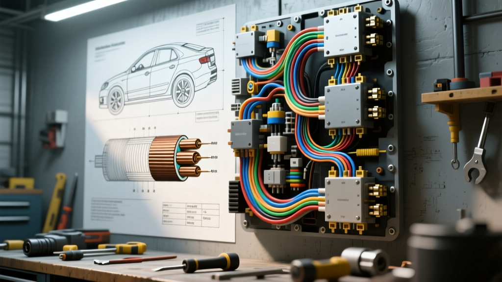
The Fallacy of Visual Estimation and Basic Calipers
When diagnosing complex automotive electrical faults, particularly in high-speed data networks or high-current EV cooling systems, the physical dimensions of the conductor are not just a suggestion—they are a strict engineering requirement. Many technicians rely on visual estimation or cheap digital calipers when measuring wire gauge in the field. This approach is fundamentally flawed when applied to modern automotive primary cable.
Standard wire gauge notch tools, designed for solid household copper, are entirely useless for automotive stranded wire. Furthermore, attempting to measure the overall diameter of a stranded bundle with digital calipers introduces massive variables. Stranded wire is not a solid cylinder; it has interstitial voids between the individual copper strands. Compressing the wire with caliper jaws flattens the bundle, yielding an inaccurate outer diameter that does not correlate to the American Wire Gauge (AWG) standard. To accurately identify mystery wiring in a hacked harness or verify OEM specifications, you must abandon outer-diameter estimation and transition to Cross-Sectional Area (CSA) calculation via micrometer measurement.
Cross-Sectional Area (CSA) vs. AWG: The Mathematical Reality
The AWG system is historically based on the cross-sectional area of the conductor, not its outer diameter. In automotive applications, wire is manufactured to SAE J1128 standards (typically GXL, TXL, or SXL insulation types). These standards dictate a specific nominal CSA in square millimeters (mm²) for each AWG size. Because automotive wire is stranded to withstand extreme vibration and thermal cycling, the true gauge can only be verified by measuring the individual strands and calculating the total copper area.
The formula for calculating the CSA of stranded automotive wire is:
CSA = (π × d² / 4) × n
- d = Diameter of a single strand (in mm)
- n = Total number of strands in the bundle
By isolating the copper from the insulation and the voids, you eliminate the guesswork. Below is the definitive reference chart for SAE J1128 GXL wire, which is the most common thin-wall insulation used in modern engine bays and chassis harnesses.
SAE J1128 GXL Wire Specification Chart
| AWG Size | Nominal CSA (mm²) | Strand Count | Single Strand Dia. (mm) | Max Overall Dia. (mm) |
|---|---|---|---|---|
| 22 AWG | 0.35 | 7 | 0.254 | 1.14 |
| 20 AWG | 0.50 | 7 | 0.305 | 1.27 |
| 18 AWG | 0.80 | 16 | 0.254 | 1.52 |
| 16 AWG | 1.30 | 19 | 0.295 | 1.91 |
| 14 AWG | 2.00 | 19 | 0.373 | 2.29 |
| 12 AWG | 3.00 | 19 | 0.465 | 2.67 |
| 10 AWG | 5.00 | 19 | 0.584 | 3.43 |
Step-by-Step Micrometer Measurement Protocol
To achieve laboratory-grade accuracy when measuring wire gauge in a vehicle, you must use an outside micrometer with a resolution of at least 0.001 inches (or 0.01 mm). Follow this strict protocol to avoid false readings:
- Isolate the Conductor: Strip back at least 3 inches of the GXL or TXL insulation using precision flush cutters. Avoid scoring the copper, as nicking alters the structural integrity and diameter of the outer strands.
- Clean the Copper: Use 99% isopropyl alcohol and a lint-free wipe to remove any oxidation, dielectric grease, or flux residue. Contaminants add microscopic layers that skew micrometer readings.
- Fan and Select: Gently fan out the stranded bundle. Select 5 random strands from different areas of the bundle (center and edges).
- Measure and Average: Use the micrometer's ratchet stop to apply consistent pressure. Measure the diameter of each of the 5 strands and calculate the average diameter (d). Do not over-tighten, as copper is soft and will compress.
- Count and Calculate: Count the total number of strands (n). Apply the CSA formula to determine the exact square millimeter area, then cross-reference the SAE J1128 chart above to identify the true AWG.
Real-World Case Study: Diagnosing CAN-Bus Impedance Faults
Consider a diagnostic scenario involving a 2018 Chevrolet Silverado K2XX platform experiencing intermittent U-codes (loss of communication) on the High-Speed GMLAN network. The GMLAN network relies on a strict 120-ohm impedance. The OEM wiring for this data bus typically utilizes 20 AWG (0.50 mm²) unshielded twisted pair. The standard GM color coding for this bus is Dark Green (CAN-H) and Light Green (CAN-L).
During a visual inspection, you discover a previous technician spliced in a replacement section of wire to repair a chafed harness near the underhood fuse block. Visually, the replacement wire looks identical to the OEM 20 AWG. However, the vehicle continues to throw U0073 (Control Module Communication Bus A Off) codes during high-vibration driving.
By applying the micrometer protocol to the spliced wire, you strip the insulation and measure the strands. The replacement wire has 16 strands measuring 0.254mm each. Running the math: CSA = (π × 0.254² / 4) × 16 = 0.80 mm². The technician unknowingly installed 18 AWG wire instead of the required 20 AWG.
While 18 AWG has lower DC resistance, the change in physical geometry alters the capacitance and characteristic impedance of the twisted pair. In high-frequency data networks operating at 500 kbps or higher, this impedance mismatch causes signal reflection and standing waves, resulting in corrupted data frames. Furthermore, the 18 AWG wire is too thick for the OEM Delphi Metri-Pack 150 series terminal crimp barrel, leading to a micro-short inside the connector housing. Accurately measuring wire gauge in this scenario immediately isolates the root cause of a failure that a standard oscilloscope trace might only show as 'noise'.
Common Pitfalls: Crimp Compression and Work Hardening
When attempting to identify wire gauge on an existing harness, never measure the wire immediately adjacent to a crimp terminal. When a terminal (such as a TE Connectivity AMP Superseal or a Yazaki connector) is crimped onto stranded wire, the copper undergoes severe mechanical compression and work hardening. The strands inside the crimp barrel are deformed, reducing the overall diameter of the bundle and altering the cross-sectional geometry.
Always measure at least 2 to 3 inches away from any crimp barrel, solder joint, or ultrasonic weld. Additionally, be wary of 'copper-clad aluminum' (CCA) wire in aftermarket stereos or cheap replacement harnesses. CCA wire has a different density and resistance profile than pure OFC (Oxygen-Free Copper). While the physical gauge might measure correctly, the ampacity and voltage drop characteristics will mimic a wire two AWG sizes smaller, leading to melted connectors in high-draw circuits like electric cooling fans or fuel pumps.
Authoritative References & Standards
For further engineering data on automotive conductor specifications and harness acceptance criteria, consult the following industry standards:
- SAE International - SAE J1128: Low Tension Primary Cable (Defines dimensional and material requirements for automotive battery and primary wiring).
- IPC/WHMA-A-620 (The definitive standard for wire harness assembly, including precise crimp and wire preparation tolerances).
- TE Connectivity Wire Gauge Chart (Excellent reference for matching AWG/mm² to specific automotive terminal crimp profiles).