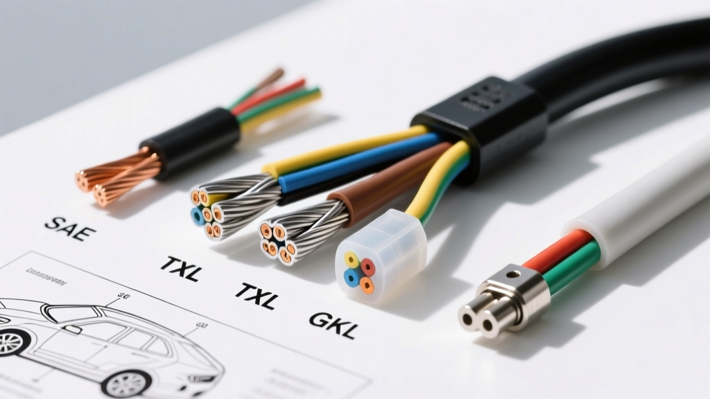
The Anatomy of Auto Wire Gauge: Beyond Standard AWG
When building a custom engine harness, restoring a classic muscle car, or upgrading a modern fuel system, selecting the correct auto wire gauge is the most critical electrical decision you will make. However, amateur builders often make the mistake of relying solely on American Wire Gauge (AWG) sizing without considering the SAE (Society of Automotive Engineers) insulation standards, strand count, and copper purity. In automotive environments, a 12 AWG wire from a hardware store is vastly inferior to a 12 AWG SAE J1128-compliant wire. The former may use brittle PVC insulation and Copper-Clad Aluminum (CCA) conductors, while the latter uses cross-linked polyethylene (XLPE) and high-strand Oxygen-Free Copper (OFC) designed to withstand 150°C engine bay temperatures, chemical exposure, and constant vibration.
This comprehensive selection guide breaks down the technical specifications of automotive wiring, comparing insulation types, voltage drop metrics, and application-specific pairing for connectors like Deutsch DT, Metri-Pack, and Weather-Pack.
SAE J1128 Insulation Types: TXL vs. GXL vs. SXL
The SAE J1128 standard dictates the performance requirements for automotive cables. The most common variants you will encounter are TXL, GXL, and SXL. All three utilize XLPE (cross-linked) insulation, which provides superior thermal and chemical resistance compared to standard PVC, but they differ significantly in wall thickness and flexibility.
| Specification | TXL (Thin Wall) | GXL (General) | SXL (Standard/Thick) |
|---|---|---|---|
| Insulation Material | Cross-Linked Polyethylene | Cross-Linked Polyethylene | Cross-Linked Polyethylene |
| Max Temperature | 125°C | 125°C | 150°C |
| Wall Thickness (18 AWG) | 0.41 mm | 0.58 mm | 0.86 mm |
| Outer Diameter (18 AWG) | 1.65 mm | 2.00 mm | 2.50 mm |
| Best Application | Dense ECU harnesses, tight looms | General chassis, engine bay routing | High-heat zones, exhaust proximity |
When to Use TXL vs. GXL
TXL is the industry standard for modern OEM engine control unit (ECU) harnesses. Because modern powertrain control modules (PCMs) utilize 60-pin to 120-pin connectors (like the Bosch ME7 or GM Gen V ECM connectors), harness bulk is a major issue. TXL’s thin wall allows you to route up to 40 conductors through a 1-inch split loom without exceeding the bend radius limits. However, TXL requires careful handling; its thin insulation is more susceptible to chafing on sharp chassis brackets. GXL is the preferred choice for aftermarket EFI builds, relay panels, and general chassis wiring where loom space is less restricted and physical abrasion resistance is prioritized.
Voltage Drop: The Silent Killer of 12V Systems
Choosing an auto wire gauge based purely on 'ampacity charts' is a dangerous practice in 12-volt automotive systems. A wire might be thick enough not to melt at 15 amps, but if it is too thin to prevent a voltage drop over a 15-foot run, your components will starve. For example, an electric fuel pump rated for 13.5V that only receives 11.5V due to wire resistance will lose up to 30% of its flow volume and overheat prematurely.
12V Voltage Drop Calculation Matrix (Per 10 Feet)
Use this reference to size your wires for maximum efficiency. Automotive standards generally dictate a maximum allowable voltage drop of 0.5V for sensitive electronics and 0.2V for critical sensor grounds.
- 22 AWG:0.32V drop @ 2 Amps (Suitable for MAP/TPS signal wires)
- 18 AWG:0.13V drop @ 5 Amps (Suitable for injectors, ignition coils)
- 14 AWG:0.08V drop @ 10 Amps (Suitable for cooling fans, solenoids)
- 10 AWG:0.03V drop @ 20 Amps (Suitable for high-pressure fuel pumps, audio amps)
- 4 AWG:0.01V drop @ 50 Amps (Suitable for starter motors, alternator charging)
Application-Specific Selection & Connector Pairings
Matching the correct auto wire gauge to the appropriate terminal and connector cavity size is essential for a reliable crimp. Mismatching wire sizes to connector pins is the leading cause of terminal push-out and intermittent open circuits.
1. EFI Sensors and Low-Current Signals (20-22 AWG)
Sensors like the Crankshaft Position Sensor (CKP), Camshaft Position Sensor (CMP), and wideband O2 sensors require precise signal integrity. Wire Choice: 22 AWG TXL. For CKP/CMP sensors, always use shielded twisted pair (STP) wire to prevent Electromagnetic Interference (EMI) from high-voltage ignition coils. Connector Pairing: Deutsch DT (Size 20 pin cavity) or Aptiv Metri-Pack 150. Color Code Standard: Red (12V Reference), Black (Sensor Ground), Green/White (Signal Return).
2. Fuel Injectors and Ignition Coils (16-18 AWG)
Modern high-impedance injectors draw 1-2 amps, while older low-impedance peak-and-hold injectors can draw up to 4 amps. Coil-on-plug (COP) systems draw brief but intense spikes of 8-10 amps. Wire Choice: 18 AWG GXL (High strand count for flexibility). Connector Pairing: EV1/EV6 injector pigtails, Metri-Pack 280 for COP harnesses. Crimp Die: Use a specific open-barrel F-crimp tool (like the Delphi/Aptiv spec crimpers) to ensure the wire bellmouth is visible, preventing insulation from being crushed inside the terminal crimp wings.
3. High-Current Actuators & Power Distribution (10-12 AWG)
Circuits powering electric water pumps, transmission controllers, and main EFI relays require robust conductors. Wire Choice: 10 AWG or 12 AWG SXL. Connector Pairing: Weather-Pack 12010822 (requires heavy-duty crimpers) or larger Metri-Pack 630 series. Pro Tip: Always use a secondary lock (TPA - Terminal Position Assurance) in Weather-Pack connectors for 10 AWG wire, as the stiffness of the thicker wire can push the terminal out of the housing during mating.
Material Purity: OFC vs. CCA
When sourcing bulk auto wire gauge spools, you will inevitably encounter Copper-Clad Aluminum (CCA). CCA wire is significantly cheaper and lighter, but it is an electrical hazard in automotive applications. Aluminum has roughly 61% of the conductivity of copper. To achieve the same ampacity as 10 AWG OFC (Oxygen-Free Copper), you would need to step up to 8 AWG CCA. Furthermore, aluminum creeps and oxidizes rapidly when exposed to engine bay humidity and thermal cycling, leading to high-resistance connections at ring terminals and fuse blocks. Always verify that your wire is stamped 'OFC' or 'SAE J1128' and avoid unmarked Amazon/eBay wiring kits.
Common Failure Modes from Incorrect Gauge Selection
Even master technicians make wiring mistakes. Here is a troubleshooting decision tree for diagnosing auto wire gauge failures:
Symptom: ECU Resets Under Heavy Load (e.g., when cooling fans kick on)
- Cause: Undersized power or ground wire gauge feeding the ECU main relay, causing a momentary voltage drop below 9V.
- Fix: Upgrade the ECU main power feed from 16 AWG to 12 AWG GXL, and ensure the ECU ground is tied directly to the engine block using a minimum 10 AWG ground strap, torqued to 25 Nm on a clean, bare-metal surface.
Symptom: Intermittent Misfire or Rough Idle
- Cause: Using unshielded 18 AWG wire for inductive crank/cam sensors, allowing ignition noise to create false teeth counts on the ECU.
- Fix: Replace signal wires with 22 AWG shielded twisted pair. Ground the shield drain wire at the ECU harness plug only (pin 42 on most Bosch ME7 harnesses), never at the sensor end, to prevent ground loops.
Symptom: Melted Fuse Block or Discolored Terminals
- Cause: Using CCA wire instead of OFC, or using a wire gauge that is too small for the circuit's continuous amperage, causing the terminal to act as a resistor and generate heat.
- Fix: Cut back the heat-damaged wire to fresh copper. Upgrade to SAE J1128 compliant OFC wire, and apply dielectric grease (like Nyogel 760G) to the fuse block terminals to prevent micro-fretting corrosion.
Final Best Practices for Harness Assembly
When assembling your harness, always follow the 80% fill rule for conduit and split loom. If your bundled auto wire gauge fills more than 80% of the loom's internal diameter, step up to the next loom size to allow for heat dissipation and wire movement. Finally, secure your harness every 6 to 8 inches using high-temperature nylon zip ties or P-clips with rubber cushions, ensuring the harness never rests directly against exhaust manifolds or sharp firewall edges. For ultimate protection in high-heat zones, wrap the harness in fiberglass fire-sleeve or expandable nylon braided sleeving.
For further reading on terminal crimp specifications and pull-test requirements, consult the Aptiv/Delphi connector datasheets and reference Waytek Wire's technical library for exact outer diameter measurements before ordering your bulk wire and split loom.