Why Guessing Wire Gauge Ruins Automotive Electrical Systems
When repairing a melted headlight harness or upgrading an alternator on a classic truck, guessing the wire gauge is a fast track to voltage drops, blown fuses, or worse—an electrical fire. Automotive wiring operates in a harsh environment characterized by high under-hood temperatures, vibration, and chemical exposure. Because of this, automotive wire is constructed differently than standard household solid-core wire. If you do not know exactly how to measure wire gauge on a stranded automotive conductor, you risk undersizing replacement circuits and overloading your vehicle's charging system.
This beginner-friendly fundamentals guide will teach you how to accurately identify, measure, and verify automotive wire gauge using precision tools, cross-sectional math, and Society of Automotive Engineers (SAE) standards.
The Critical Difference Between AWG and SAE Wire Standards
Before grabbing your calipers, you must understand the difference between American Wire Gauge (AWG) and SAE standards. Standard AWG sizing was originally developed for solid, single-core copper wire. However, automotive primary wire—such as TXL, GXL, and SXL cross-linked polyethylene (XLPE) insulated wire—is heavily stranded to withstand engine vibration without fatiguing and breaking.
Because stranded wire has microscopic air gaps between the individual copper filaments, a stranded 12 AWG wire will actually have a slightly larger overall physical diameter than a solid 12 AWG wire. To account for this, the automotive industry relies on the SAE J1128 Standard. SAE J1128 dictates the minimum cross-sectional area of the copper itself, ignoring the insulation and the air gaps. When measuring automotive wire, we are ultimately trying to determine the total cross-sectional area of the copper strands to match it to the correct AWG equivalent.
Tools Required to Measure Stranded Automotive Wire
Do not attempt to measure wire gauge by holding it up to a ruler or using the stripping notches on a cheap pair of combination pliers. You need the following tools:
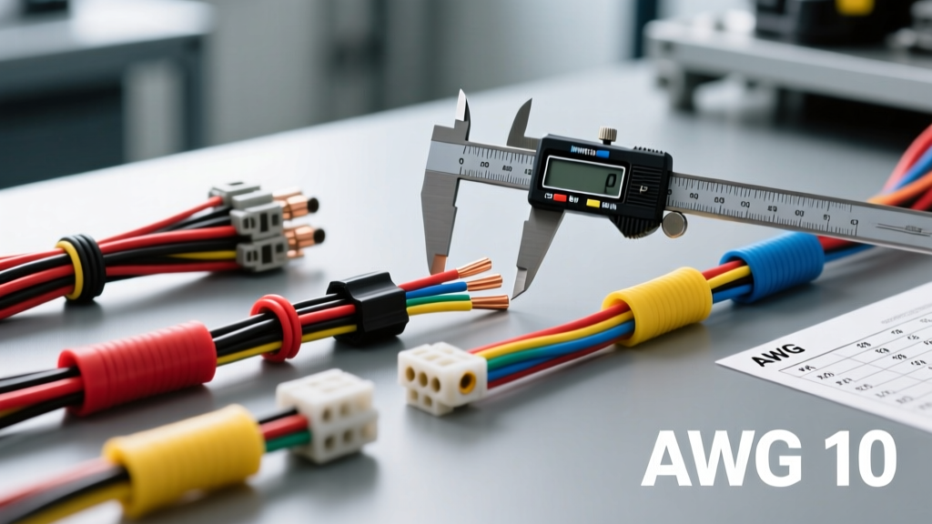
- Digital Calipers: Capable of measuring to 0.001 inches (one-thousandth of an inch) or 0.01 millimeters.
- Precision Wire Strippers: To remove the XLPE or PVC insulation without nicking or scraping the copper strands, which alters the diameter.
- Jeweler's Loupe or Magnifying Glass: Optional, but highly recommended for counting individual strands on smaller gauge wires (18 to 22 AWG).
- Calculator: For converting physical measurements into Circular Mils.
Step-by-Step: How to Measure Wire Gauge with Calipers
Step 1: Strip the Insulation Correctly
Cut a small section of the wire you need to identify. Using your precision wire strippers, carefully remove about 1/2 inch of the insulation. Automotive GXL wire has a very thin, tough insulation layer compared to standard THHN house wire. Ensure you do not compress or deform the stranded copper bundle during this process. If the strands are splayed or flattened, your measurement will be inaccurate.
Step 2: Measure the Conductor Bundle Diameter
Close the jaws of your digital calipers gently around the bare, exposed copper bundle. Do not squeeze tightly, as copper strands will compress, giving you a falsely small reading. Record the diameter in inches. For example, a typical automotive 12 AWG stranded bundle will measure approximately 0.089 inches in diameter.
Step 3: Calculate Cross-Sectional Area (The Circular Mil Method)
To definitively identify the AWG size based on your physical measurement, you must convert your inch reading into Circular Mils (CM). A circular mil is a unit of area used specifically for wire cross-sections.
- Convert your inch measurement to mils (1 inch = 1,000 mils). If your caliper reads 0.089 inches, that is 89 mils.
- Square that number to find the Circular Mils. (89 x 89 = 7,921 CM).
- Compare your result to an AWG chart. 7,921 CM is very close to 6,530 CM (Standard 12 AWG) or 10,380 CM (Standard 10 AWG). Wait, why the discrepancy?
Expert Note: Measuring the outside diameter of a stranded bundle includes the air gaps between strands. To get the exact pure copper area, you must measure a single strand, calculate its area, and multiply by the total strand count. According to Pacer Group's technical resources, a standard 12 AWG automotive wire typically features 19 strands of 0.0179-inch wire. (17.9 mils squared = 320.41 CM per strand. 320.41 x 19 strands = 6,087 CM, which perfectly aligns with the 12 AWG standard).
Automotive Wire Gauge to Diameter Reference Chart
Use the following reference table when measuring bare copper bundles or single strands in automotive harnesses. This chart reflects standard SAE J1128 primary wire configurations.
| AWG Size | Typical Stranding | Single Strand Diameter (in) | Total Copper Area (Circular Mils) | Max Amps (Chassis Wiring) |
|---|---|---|---|---|
| 18 AWG | 16 strands | 0.0100 | 1,600 | 6A - 10A |
| 16 AWG | 19 strands | 0.0113 | 2,580 | 10A - 13A |
| 14 AWG | 19 strands | 0.0142 | 4,110 | 15A - 20A |
| 12 AWG | 19 strands | 0.0179 | 6,530 | 20A - 25A |
| 10 AWG | 19 strands | 0.0226 | 10,380 | 30A - 40A |
| 8 AWG | 19 strands | 0.0285 | 16,510 | 40A - 55A |
| 4 AWG | 19 strands | 0.0453 | 41,740 | 70A - 100A |
Common Automotive Wire Gauges and Real-World Applications
Understanding how to measure wire gauge is only half the battle; knowing what gauge belongs in specific vehicle circuits is what separates novices from professionals. Here is how gauge sizing applies to real automotive systems:
ECU Sensors and Low-Current Signals (18 to 22 AWG)
Sensor circuits require minimal amperage but demand high signal integrity. For example, on a GM LS-based engine, the Oxygen (O2) sensor heater circuit typically uses 18 AWG Pink wire, while the low-level signal wire returning to the Powertrain Control Module (PCM) uses 20 AWG Purple wire, often wrapped in a braided metallic shield to prevent electromagnetic interference (EMI). These wires terminate in small cavity Metripack 150 or Weather-Pack connectors.
Lighting and Accessory Circuits (14 to 16 AWG)
Standard lighting circuits, such as H11 low-beam headlights or interior dome lights, generally rely on 16 AWG or 14 AWG wire. If you are upgrading to high-draw halogen bulbs or adding off-road LED light bars, you must upgrade the harness to 12 AWG and utilize a 30-amp automotive relay. Running 40 amps of LED draw through a factory 16 AWG headlight switch will melt the switch contacts and the bulkhead connector.
High-Amperage Charging and Starting (4 to 8 AWG)
The main battery ground strap, alternator B+ output terminal, and starter motor solenoid feed require massive current transfer. A modern 150-amp alternator requires a minimum of 4 AWG copper cable (often Red with a heavy-duty ring terminal) to prevent voltage drop. Ford frequently uses Black with an Orange stripe for heavy alternator output circuits in their OEM harnesses.
Troubleshooting Voltage Drop from Undersized Wiring
Even if you measure the wire gauge correctly and replace it with the same AWG, you may still experience electrical failures if the circuit length has increased. According to the classic Delphi Automotive Electrical Handbook, wire gauge must be scaled up based on the total length of the circuit to compensate for resistance.
Symptom: Your aftermarket fuel pump (drawing 15 amps) is starving at high RPM, and the pump whines loudly.
Diagnosis: Perform a voltage drop test. Connect your multimeter's red probe to the battery positive and the black probe to the power pin inside the fuel pump's Metripack 280 connector. With the key in the 'Run' position, you should read no more than 0.2V to 0.5V of drop. If you read 2.5V of drop, your wire is either severely corroded, or you have used 16 AWG wire for a 15-foot run when 12 AWG was required.
Fix: Always calculate the total circuit length (Positive wire + Ground wire). If your fuel pump is 12 feet from the battery, your total circuit length is 24 feet. For a 15-amp continuous draw over 24 feet, 14 AWG will result in a 3% voltage drop, which is acceptable. However, if you route the wire through the trunk and back (totaling 35 feet), you must step up to 12 AWG to maintain optimal fuel pressure.
Pro-Tips for Automotive Wiring Success
- Never use household THHN wire: It is stranded, but the PVC insulation will melt against a hot exhaust manifold and absorb moisture. Always use SAE J1128 approved GXL or TXL cross-linked wire.
- Crimp, don't solder: While soldering seems secure, solder wicks up into the stranded wire under heat, creating a rigid point that will snap under engine vibration. Use a proper ratcheting crimper and adhesive-lined heat shrink terminals.
- Account for under-hood heat: Wire ampacity ratings are based on ambient room temperature. A 12 AWG wire rated for 25 amps in the cabin may only safely handle 15 amps when routed inches away from a 200°F exhaust header. Always upsize gauge for engine bay routing.
Mastering how to measure wire gauge ensures that every repair, upgrade, and custom harness you build operates safely and efficiently. By relying on digital calipers, circular mil calculations, and SAE standards rather than visual guesswork, you guarantee the longevity and reliability of your vehicle's electrical system.