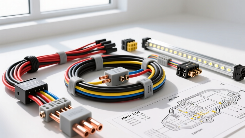
Why Low Voltage DC Demands Precision Wire Sizing
When executing a 12V DC electrical upgrade—such as installing an auxiliary fuse block, off-road LED light bars, or a dual-battery isolator system—the rules of wire sizing change drastically compared to household 120V AC wiring. In low voltage DC systems, current (amperage) is significantly higher to deliver the same wattage. This high current generates heat and induces voltage drop across the conductor. If you rely on a generic household wire chart, your off-road lighting will flicker, your relays will chatter, and your wire insulation may melt in the engine bay.
To ensure safety and optimal performance, automotive electricians rely on a dedicated low voltage wire gauge chart that accounts for chassis wiring conditions, ambient engine bay temperatures, and the strict 3% maximum voltage drop rule recommended for critical 12V automotive electronics. This guide provides the exact specifications needed for your next overland or off-road 12V modification project.
The Physics of Voltage Drop in 12V Automotive Systems
Voltage drop is the reduction in electrical potential between the power source and the load. In a 120V AC system, a 2-volt drop is negligible (less than 2%). However, in a 12V DC automotive system, a 2-volt drop represents a massive 16% loss. When an LED light bar designed for 13.8V receives only 11.5V, it will draw more current to compensate for the lost wattage, which further exacerbates the heat and voltage drop in a dangerous thermal runaway loop.
According to the Blue Sea Systems Circuit Sizing guidelines, wire must be sized not just for the maximum ampacity of the load, but for the total round-trip length of the circuit (positive and negative leads) to maintain a voltage drop below 3%. Furthermore, wire routed through an engine bay must be derated due to ambient temperatures frequently exceeding 50°C (122°F).
The Ultimate Low Voltage Wire Gauge Chart for 12V Upgrades
The following low voltage wire gauge chart is calibrated for SAE J1128 GXL (thin-wall, 125°C rated) automotive primary wire. The 'Max Length' column calculates the maximum round-trip circuit length allowed to maintain a 3% voltage drop at 12V DC.
| AWG Size | Cross-Section (mm²) | Max Amps (Chassis)* | Max Amps (Power Trans.) | Ohms per 1,000 ft | Max 12V Length (10A Load) | Max 12V Length (20A Load) |
|---|---|---|---|---|---|---|
| 18 AWG | 0.82 | 16A | 5A | 6.51 | 11 ft | 5.5 ft |
| 16 AWG | 1.31 | 22A | 10A | 4.09 | 17 ft | 8.5 ft |
| 14 AWG | 2.08 | 32A | 15A | 2.57 | 28 ft | 14 ft |
| 12 AWG | 3.31 | 41A | 20A | 1.61 | 44 ft | 22 ft |
| 10 AWG | 5.26 | 55A | 30A | 1.01 | 70 ft | 35 ft |
| 8 AWG | 8.37 | 73A | 50A | 0.64 | 112 ft | 56 ft |
| 6 AWG | 13.30 | 101A | 65A | 0.40 | 178 ft | 89 ft |
| 4 AWG | 21.15 | 135A | 85A | 0.25 | 285 ft | 142 ft |
*Chassis wiring assumes a single wire in free air or bundled with no more than 3 other current-carrying conductors. For wires routed inside corrugated loom in high-heat engine bays, derate max chassis amps by 20%.
Project Blueprint: Overland Auxiliary Fuse Block & Lighting Upfit
Let us apply this low voltage wire gauge chart to a real-world modification: installing an auxiliary fuse block in the engine bay to power a 40-inch LED light bar (20A draw) and four cubic LED rock lights (combined 8A draw).
Step 1: Main Battery Feed to the Auxiliary Bus
The main feed from the vehicle's positive battery terminal to the auxiliary fuse block must handle the combined potential load of all accessories, plus a 25% safety buffer. If your bus is rated for 60A total, you must size the wire for at least 75A. According to our chart, 6 AWG SAE GXL wire is required.
- Wire Color: Red (SAE standard for constant 12V+ battery feed).
- Protection: Install a 70A ANL fuse or MAXI circuit breaker within 7 inches of the battery positive terminal to protect the main feed in case of a dead short.
- Termination: Use a heavy-duty 6 AWG ring terminal, crimped with a hex-crimp die, and secured to the battery post with a torque of 10-12 Nm.
Step 2: Relay Trigger and Switch Wiring
To prevent routing high-amperage 12 AWG wire through the firewall and into the cabin, we use a standard Bosch-style ISO mini relay (5-pin) mounted in the engine bay. The relay switches the high-current load, while the cabin switch only handles the low-current trigger signal.
- Pin 86 (Relay Coil 12V+): Run 18 AWG wire from an ignition-switched fuse in the OEM fuse box to the cabin toggle switch, then to Pin 86.
- Pin 85 (Relay Coil Ground): Run 18 AWG black wire to a clean, bare-metal chassis ground.
- Cabin Switch: Use an IP67-rated toggle switch. Because the relay coil draws less than 0.2A, the 18 AWG wire easily handles the trigger circuit with virtually zero voltage drop over a 15-foot run.
Step 3: Load Wiring to LED Light Bars and Pods
The 40-inch LED light bar draws approximately 18A at 13.8V. The run from the relay (mounted in the engine bay) to the roof rack is roughly 12 feet (24 feet round trip).
- Pin 30 (Relay Power In): 10 AWG red wire from the auxiliary fuse block (protected by a 25A blade fuse).
- Pin 87 (Relay Power Out): 10 AWG red wire routed through the firewall and up the A-pillar to the light bar. (While 12 AWG is rated for 20A, the 24-foot round trip exceeds the 22-foot max length for a 20A load on our chart, necessitating the bump to 10 AWG to prevent voltage drop).
- Ground: 10 AWG black wire from the light bar directly to a dedicated chassis ground point, bypassing the roof rack tubing which often has poor continuity due to powder coating.
Connector Selection and Crimping Standards
Using the correct wire gauge is useless if the termination points introduce high resistance. For off-road applications subject to water, mud, and extreme vibration, standard butt splices will fail.
- Deutsch DT Series: Use 2-pin or 4-pin Aptiv Weather-Pack or Deutsch DT connectors for all connections at the light bar and relay. These feature silicone seals that prevent moisture ingress and corrosion.
- Heat Shrink Terminals: For inline splices, use only adhesive-lined, dual-wall marine heat shrink butt connectors. The inner meltable adhesive seals the wire strands against capillary action, preventing water from wicking under the insulation.
- Crimping: Never use pliers to crimp automotive terminals. Use a ratcheting crimper with the correct die profile (e.g., an 'F' die for Weather-Pack stamped terminals) to ensure a gas-tight cold weld between the copper strands and the brass terminal.
Common Failure Modes in Aftermarket 12V Upgrades
When modifiers ignore the low voltage wire gauge chart and attempt to save money by undersizing wire, several distinct failure modes emerge:
- Relay Chatter: If the trigger wire (Pin 86) is too thin or the ground (Pin 85) is poor, the voltage reaching the relay coil drops below the 9V pull-in threshold. The relay will rapidly click on and off, generating massive voltage spikes that can fry sensitive ECU modules on the vehicle's CAN bus.
- Thermal Runaway in Loom: Bundling undersized wires tightly inside split-loom tubing traps heat. A 12 AWG wire rated for 41A in free air may only safely carry 25A inside a tightly packed engine bay loom. The insulation softens, leading to a dead short against the chassis.
- PWM Flickering: Modern LED light bars use Pulse Width Modulation (PWM) drivers. If the wire gauge is too small, the voltage drop during the 'on' pulse causes the driver to reset, resulting in a visible strobe effect at night.
Final Wiring Verification
Before sealing the firewall grommets and zip-tying the loom, perform a loaded voltage drop test. Connect a digital multimeter across the battery positive and the light bar's positive input pin while the lights are turned on. A reading of 13.4V at the battery and 13.0V at the light bar confirms a 0.4V drop (well within the 3% threshold). By strictly adhering to this low voltage wire gauge chart and utilizing proper SAE-rated materials, your off-road electrical upgrades will remain reliable through thousands of miles of punishing terrain.