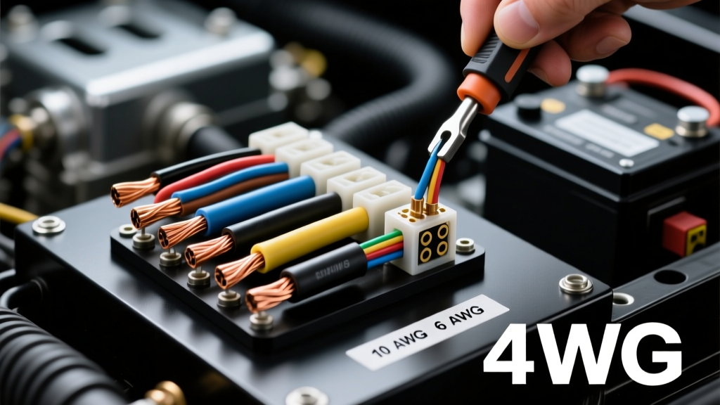
The Physics of the Return Path: Why Grounding Wire Gauge Matters
In automotive electrical systems, the ground path is not merely a safety feature; it is the critical return half of every DC circuit. Selecting the correct grounding wire gauge is fundamentally about managing voltage drop and thermal capacity. According to Ohm’s Law (V = I × R), any resistance in the ground path will result in a voltage drop that subtracts directly from the voltage available to the load. If an ECU requires 5.0V for a stable sensor reference, but the ground path has 0.15V of drop due to an undersized gauge or poor termination, the ECU reads 4.85V, leading to skewed fuel trims, erratic transmission shifts, or phantom OBD-II codes.
Unlike positive feeds which are typically protected by fuses, main ground paths often lack overcurrent protection. Therefore, the grounding wire gauge must be sized not only for continuous operational current but also for peak transient loads and fault currents. The SAE J1128 standard for low-tension primary cable outlines the thermal limits of automotive wire insulation, but the copper cross-section dictates the actual ampacity and resistance per foot.
Grounding Wire Gauge Comparison & Selection Chart
The following reference chart details standard AWG sizes, their metric equivalents, maximum continuous ampacity in high-temperature under-hood environments (up to 125°C), and their primary automotive applications.
| AWG Size | Metric (mm²) | Resistance (mΩ/ft) | Max Ampacity (Engine Bay) | Primary Application | Standard Terminal Hardware |
|---|---|---|---|---|---|
| 1/0 AWG | 53.5 mm² | 0.098 | 150A - 170A | Main battery ground, High-output alternator returns | 5/16" or 3/8" Ring Terminal |
| 2 AWG | 33.6 mm² | 0.156 | 120A - 130A | V8 Engine block to chassis, Starter motor return | 5/16" Ring Terminal |
| 4 AWG | 21.1 mm² | 0.248 | 85A - 95A | 4-Cylinder engine grounds, Secondary battery links | 1/4" or 5/16" Ring Terminal |
| 8 AWG | 8.37 mm² | 0.628 | 40A - 50A | Body to frame straps, Fuel pump module grounds | 1/4" Ring Terminal |
| 12 AWG | 3.31 mm² | 1.588 | 20A - 25A | ECU main power ground, Headlight circuit returns | #10 Ring Terminal |
| 16 AWG | 1.31 mm² | 4.016 | 10A - 12A | Sensor signal grounds, CAN-bus shield drains | #8 or #10 Ring / Spade |
Material Selection: OFC, Tinned, and the CCA Trap
When sourcing wire for automotive grounds, the metallurgy is just as important as the gauge. The market is flooded with CCA (Copper-Clad Aluminum) wire, which is fundamentally unsuited for critical automotive grounding.
1. Oxygen-Free Copper (OFC)
OFC is the baseline standard for high-performance automotive wiring. It offers 100% IACS (International Annealed Copper Standard) conductivity. For main battery-to-chassis grounds, bare OFC wire with high-temperature cross-linked polyethylene (XLPE) insulation is ideal.
2. Tinned Copper (Marine/Under-Hood Grade)
For engine-to-chassis grounds or any grounding wire routed near exhaust manifolds or exposed to road salt, tinned copper is mandatory. The tin coating prevents galvanic corrosion and oxidation of the copper strands. Bare copper turns green (copper oxide/carbonate) and black (copper sulfide) over time; both compounds are highly resistive semiconductors that will choke a ground circuit, causing alternator whine and dimming headlights.
3. Copper-Clad Aluminum (CCA) - AVOID
CCA wire features an aluminum core with a thin copper wash. Aluminum has only 61% of the conductivity of copper by volume. Furthermore, aluminum suffers from 'cold creep'—under the constant torque of a ring terminal, aluminum deforms over time, loosening the connection. Combined with rapid galvanic corrosion when mated to steel chassis points, CCA ground wires are a leading cause of intermittent electrical failures in aftermarket builds.
Application-Specific Grounding Strategies
The Master Ground: Battery to Chassis
The main battery ground must handle the entirety of the vehicle's electrical return current, including starter motor cranking loads which can exceed 400A for brief durations. Selection: Use a minimum of 1/0 AWG OFC wire. Route it from the battery negative post directly to a clean, bare-metal point on the chassis or engine block closest to the battery. Do not rely on factory 4 AWG wires if you have upgraded to a high-torque starter or a 200A+ alternator.
Engine Block to Chassis (The Alternator Return)
The alternator generates massive AC ripple and DC current. Its case is grounded to the engine block, which sits on rubber motor mounts. Rubber isolates the block electrically. Selection: Use a 2 AWG or 4 AWG flexible braided ground strap or heavily stranded wire. Braided flat straps are superior here because they offer immense surface area, which reduces high-frequency impedance, effectively filtering out RFI (Radio Frequency Interference) that causes stereo alternator whine.
ECU and Sensor Signal Grounds
Modern ECUs use dedicated 'signal grounds' for O2 sensors, MAP sensors, and TPS. These circuits carry less than 1 Amp but are highly sensitive to millivolt fluctuations. Selection: 16 AWG or 18 AWG wire. OEM Color Codes: GM typically uses Black with a White tracer for main grounds and Black/Light Green for sensor grounds. Ford often uses Black/Yellow. Always verify pinouts using a factory service manual or resources like Painless Performance Wiring Manuals before tapping into ECU ground planes.
Hardware, Termination, and Corrosion Prevention
A 1/0 AWG wire is useless if terminated with a cheap, open-barrel crimp terminal bolted to a painted surface. Ground failures occur at the termination, not in the wire itself.
Terminal Crimping and Sealing
Use closed-barrel, heavy-duty copper ring terminals. Crimp using a hydraulic or hex-indent crimping tool to ensure a gas-tight connection. Follow the crimp with adhesive-lined dual-wall heat shrink. The adhesive melts and seals the wire entry point, preventing capillary action from drawing moisture under the insulation and corroding the strands from the inside out.
Mating Surface Preparation
Never ground to paint, powder coat, or rust. Use a flap disc or sandpaper to expose bare, shiny metal. The grounding hole should be tapped with a spiral-flute tap to remove debris. For aluminum engine blocks, apply a zinc-rich anti-oxidant joint compound (like Noalox or Penetrox) to the mating surface to prevent galvanic corrosion between the copper lug and aluminum block.
Expert Note: Do not use dielectric grease under the terminal. Dielectric grease is an insulator. Use it only to coat the outside of the completed connection to seal out moisture.
Hardware and Torque Specifications
- M6 (6mm) bolt to Aluminum Block: 7 - 9 ft-lbs. Use a serrated flange nut or a star washer to bite through microscopic oxidation layers.
- M8 (8mm) bolt to Cast Iron Block/Steel Frame: 15 - 18 ft-lbs.
- 3/8" Battery Terminal Stud: 8 - 10 ft-lbs. Over-torquing lead posts or side-terminal adapters will strip the soft threads.
Diagnostic Protocol: Testing Ground Integrity
Visual inspection is insufficient for diagnosing ground faults. A wire may look intact while suffering from internal strand breakage or severe terminal corrosion. The only valid diagnostic method is the Voltage Drop Test, a staple procedure taught in AutoShop 101 Electrical Circuits training.
- Set your digital multimeter to the DC Millivolt (mV) scale.
- Turn the circuit ON (or crank the engine for starter ground tests). Current must be flowing.
- Place the Red probe on the negative terminal of the battery.
- Place the Black probe on the metal casing of the load component (e.g., starter case, alternator case, ECU shell).
- Read the voltage drop. The multimeter is measuring the resistance of the ground path expressed as voltage.
Acceptable Voltage Drop Thresholds:
- Starter Motor Ground Path: Maximum 0.10V (100mV) during cranking.
- Alternator Case to Battery Negative: Maximum 0.05V (50mV) at 2000 RPM with loads on.
- ECU / Sensor Signal Grounds: Maximum 0.02V (20mV). Anything higher will skew 5V reference sensors.
- Lighting / Accessory Grounds: Maximum 0.20V (200mV).
If your reading exceeds these thresholds, move the Black probe incrementally closer to the battery along the ground path until the voltage drop disappears. The exact point where the voltage drops to near zero is the location of your high-resistance fault—usually a loose, corroded, or undersized terminal connection.