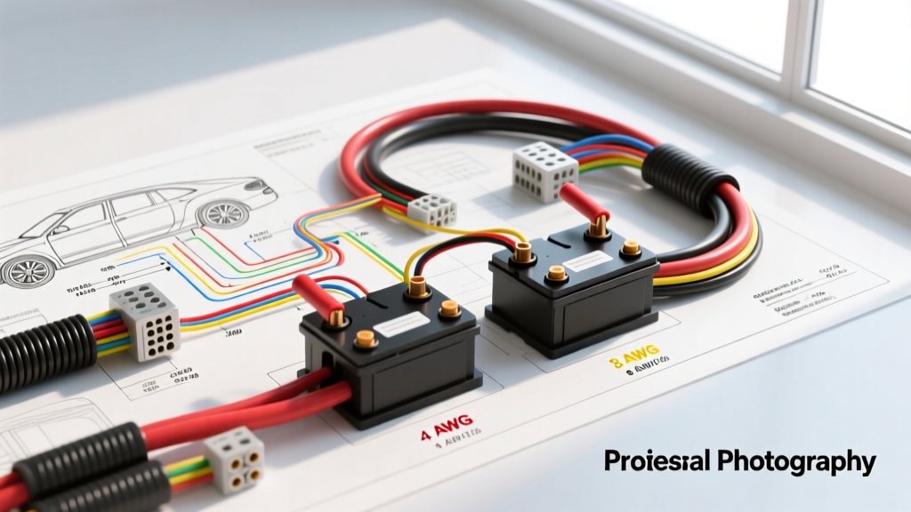
Introduction to High-Current Automotive Routing
When integrating a dual-battery management system and a 12,000-lb winch into a late-model 4x4 (such as a 2021 Ford Bronco or Toyota Tacoma), relying on generic internet ampacity charts is a recipe for melted insulation and voltage starvation at the ECU. A proper wire gauge calculation based on exact routing distances, ambient engine bay temperatures, and specific voltage drop tolerances is mandatory. This complete wiring diagram walkthrough dissects a high-current auxiliary setup, segment by segment, demonstrating exactly how to size, route, and terminate heavy-gauge automotive cables.
The Core Formula: Voltage Drop & Wire Gauge Calculation
Automotive electrical systems operate nominally at 12.6V (engine off) and 14.4V (alternator charging). The Society of Automotive Engineers (SAE) and marine ABYC standards dictate that critical electronics (ECUs, fuel pumps, ignition) should not experience more than a 3% voltage drop (0.38V at 12.6V). Resistive and inductive loads like winch motors can tolerate up to a 10% drop.
To perform an accurate wire gauge calculation, we use the Circular Mil (CM) formula:
CM = (2 x K x I x L) / VD
- K = Specific resistance of copper (12.9 ohms per mil-foot at 75°C)
- I = Maximum continuous current in Amps
- L = One-way wire length in feet
- VD = Allowable voltage drop
Once the required CM is calculated, we cross-reference it with standard AWG charts and apply temperature derating factors for under-hood routing, referencing SAE J1128 Low Tension Primary Cable Standards for insulation thermal limits.
Complete Wiring Diagram Walkthrough: Dual Battery & Winch Contactor
Below is a segment-by-segment breakdown of a high-draw auxiliary wiring harness. We will calculate the exact AWG required for each run, select the appropriate SAE cable jacket, and specify the overcurrent protection.
Segment A: High-Output Alternator to Primary Battery
- Load: 250A High-Output Alternator
- One-Way Length: 3.5 feet
- Target Voltage Drop: 3% (0.43V at 14.4V charging)
Wire Gauge Calculation:
CM = (2 x 12.9 x 250 x 3.5) / 0.43 = 52,558 CM.
Standard 2 AWG wire is 66,360 CM, which mathematically satisfies the requirement. However, this cable routes past the exhaust manifold where ambient temperatures exceed 100°C. Standard PVC insulation will degrade, and copper resistance increases with heat. Therefore, we derate and step up to 1/0 AWG (105,600 CM) using SAE Type SXL (125°C rated) cross-linked polyethylene jacket wire. We protect this circuit with a 300A Littelfuse MEGA fuse mounted within 7 inches of the battery positive post.
Segment B: Primary Battery to Smart Isolator / Solenoid
- Load: 200A continuous max (charging secondary battery and running auxiliary busbars)
- One-Way Length: 8.0 feet
- Target Voltage Drop: 3% (0.38V at 12.6V)
Wire Gauge Calculation:
CM = (2 x 12.9 x 200 x 8.0) / 0.38 = 108,631 CM.
1/0 AWG (105,600 CM) is slightly undersized for a strict 3% drop over this distance. We must upgrade to 2/0 AWG (133,072 CM). This heavy cable requires routing through the firewall or along the inner fender well, protected by split-loom and secured every 12 inches with UV-resistant zip ties to prevent chassis chafing.
Segment C: Isolator to Secondary Battery (Rear Cargo Area)
- Load: 150A continuous
- One-Way Length: 14.0 feet
- Target Voltage Drop: 3% (0.38V)
Wire Gauge Calculation:
CM = (2 x 12.9 x 150 x 14.0) / 0.38 = 142,578 CM.
This requires 3/0 AWG (167,772 CM). Because 3/0 AWG is exceptionally stiff and difficult to route through factory frame rail grommets, the professional alternative is to run two parallel 1/0 AWG cables (combined 211,200 CM). Both parallel runs must be the exact same length to ensure equal resistance and balanced current sharing. A 200A MEGA fuse is installed at the isolator output, and a second 200A fuse is placed at the secondary battery terminal.
Segment D: Secondary Battery to Winch Contactor
- Load: 400A peak (intermittent duty cycle)
- One-Way Length: 4.0 feet
- Target Voltage Drop: 10% (1.26V acceptable for inductive motor loads)
Wire Gauge Calculation:
CM = (2 x 12.9 x 400 x 4.0) / 1.26 = 32,761 CM.
Mathematically, 4 AWG (41,740 CM) is sufficient. However, winch cables are subjected to extreme physical abuse, vibration, and high inrush currents that generate rapid heat. We override the baseline math and specify 1/0 AWG EPDM Welding Cable. Welding cable features thousands of fine 30 AWG strands, offering superior flexibility and vibration resistance compared to standard automotive battery cable. This segment is protected by a 500A ANL fuse.
Technical Specification & AWG Reference Table
| Circuit Segment | Max Amps | Length (ft) | Target VD% | Calc. CM | Selected AWG | Overcurrent Protection |
|---|---|---|---|---|---|---|
| Alt to Primary Bat | 250A | 3.5 | 3% | 52,558 | 1/0 AWG (SXL) | 300A MEGA |
| Primary to Isolator | 200A | 8.0 | 3% | 108,631 | 2/0 AWG (SXL) | 250A MEGA |
| Isolator to Sec Bat | 150A | 14.0 | 3% | 142,578 | 2x 1/0 AWG Parallel | 200A MEGA (x2) |
| Sec Bat to Winch | 400A | 4.0 | 10% | 32,761 | 1/0 AWG Welding | 500A ANL |
Note: Fuse sizing is based on the ampacity of the wire and the continuous load, adhering to Littelfuse MEGA/AMG Automotive Fuse Specifications for time-delay characteristics during motor inrush.
Connector Types, Terminals, and Crimping Standards
A flawless wire gauge calculation is useless if the termination introduces high resistance. For 1/0 AWG and 2/0 AWG cables, standard stamped brass battery clamps are unacceptable. You must use heavy-duty, closed-barrel copper lugs (e.g., 3/8" or M10 ring terminals).
The Hex-Crimp Method
Never use indent-style crimpers on high-current battery cables. Indent crimps leave voids inside the barrel where moisture can ingress, leading to galvanic corrosion and green copper oxide buildup (a primary cause of voltage drop). Use a dedicated hydraulic or mechanical hex-crimp tool (such as the TEMCo HD-50). The hex die compresses the copper barrel uniformly around the strands, creating a cold-weld that is mechanically stronger than the wire itself.
Sealing and Torque Specifications
After crimping, seal the barrel entry point with 3M ITCSK adhesive-lined heat shrink. The inner thermoplastic adhesive melts and flows into the wire strands, creating a watertight seal that prevents capillary action from drawing moisture under the insulation. When attaching M10 lugs to busbars or battery terminals, torque the hardware to 11 Nm to 15 Nm (97 to 132 in-lbs) using a calibrated torque wrench. Under-torquing leads to micro-arcing and melted terminals; over-torquing can stretch the copper lug or crack cast lead battery posts.
Real-World Failure Modes & Troubleshooting
Even with perfect wire gauge calculations, secondary failure modes can plague high-draw automotive systems. Watch for these specific symptoms:
- EFI Relay Chatter: If the engine stalls under heavy winch load, the winch circuit is likely sharing a ground bus with the ECU, or the primary battery cable voltage drop exceeds 3%. The ECU sees voltage dip below 10.5V, causing the main relay to drop out. Fix: Isolate winch grounds to a dedicated chassis point, bare-paint the metal, and treat with No-Ox-ID conductive grease.
- Alternator Whine in Audio/Comms: High-current charging wires routed parallel to CAN-bus or RCA cables will induce electromagnetic interference (EMI). Fix: Cross high-amp DC cables and low-voltage signal wires at strict 90-degree angles. Never zip-tie them together.
- Isolator Overheating: If the smart isolator or continuous-duty solenoid is hot to the touch, the internal contacts are pitted, or the control wire (usually 12 AWG or 14 AWG) is suffering voltage drop, preventing the coil from pulling the contactor fully closed. Fix: Verify the solenoid trigger wire with a multimeter; it must see at least 11.5V to maintain a solid magnetic latch.
Summary
Executing a rigorous wire gauge calculation ensures your auxiliary automotive systems operate safely and efficiently. By respecting the physics of voltage drop, selecting SAE-rated high-temperature insulation, and utilizing proper hex-crimp terminations, you build a harness capable of surviving the harshest off-road and heavy-duty environments. For further reading on DC marine and auxiliary vehicle wiring standards, consult the Blue Sea Systems ABYC E-11 DC Wiring Guidelines, which heavily inform modern overland and 4x4 electrical best practices.