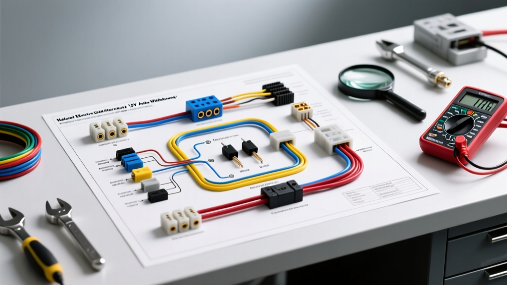
Bridging the Gap: Building Codes vs. Automotive DC Systems
When automotive fabricators, EV conversion specialists, and off-road engineers design high-current 12V DC systems, they frequently encounter a critical crossroads: the availability of wire. Local hardware stores and electrical suppliers stock THHN/THWN building wire sized according to the National Electrical Code (NEC / NFPA 70). However, relying strictly on a national electric code wire gauge chart for automotive applications can lead to catastrophic voltage drop, overheated insulation, and electrical fires. This complete wiring diagram walkthrough bridges the gap between NEC ampacity ratings and SAE J1128 automotive standards, providing a real-world guide to sizing, routing, and terminating high-amperage DC circuits.
NEC vs. SAE: Technical Specification Chart
The fundamental difference lies in the environment and the current type. The NEC chart is designed for alternating current (AC) in stationary, climate-controlled, or conduit-protected environments. Automotive wiring deals with direct current (DC), extreme under-hood temperatures (up to 125°C), vibration, and corrosive elements. Furthermore, DC systems suffer from severe voltage drop over distance compared to high-voltage AC systems.
| AWG Size | NEC Ampacity (75°C Column) | SAE Auto Max Amp (10ft Run) | Primary Automotive Use Case |
|---|---|---|---|
| 10 AWG | 35 Amps | 30 Amps | Fuel pumps, high-beam lighting, power windows |
| 8 AWG | 50 Amps | 40 Amps | Electric cooling fans, mid-range audio amplifiers |
| 4 AWG | 85 Amps | 60 Amps | Alternator output upgrades, EV battery module links |
| 1/0 AWG | 150 Amps | 120 Amps | Dual-battery isolator feeds, heavy-duty winch power |
| 4/0 AWG | 260 Amps | 210 Amps | EV main traction battery cables, starter motor feeds |
Note: The NEC ampacities assume no more than three current-carrying conductors in a raceway and an ambient temperature of 30°C (86°F). Under-hood automotive ambient temperatures routinely exceed 80°C, requiring severe derating if NEC charts are blindly applied.
Complete Wiring Diagram Walkthrough: 12,000 lb Winch & Control Circuit
To illustrate how to properly adapt a national electric code wire gauge chart for a 12V automotive application, we will walk through the complete wiring diagram of a 12,000 lb off-road winch. At stall load, this winch can draw upwards of 450 Amps. A standard NEC chart might suggest 250 kcmil copper for 255 Amps, but winching is an intermittent duty cycle, and DC voltage drop is the primary enemy.
Phase 1: High-Current Power Feed (Battery to Solenoid)
The first leg of the diagram runs from the positive battery terminal to the heavy-duty continuous-duty solenoid mounted in the engine bay.
- Wire Selection: 1/0 AWG SAE GXL (Cross-linked polyethylene) stranded copper. While a hardware store might sell 1/0 AWG THHN building wire, THHN uses a nylon outer jacket that degrades rapidly when exposed to automotive fluids, oil, and under-hood heat. GXL is rated for 125°C and resists chemical breakdown.
- Color Code: SAE Red. Warning: Do not use NEC color coding (Black for hot, White for neutral) in an automotive harness. Automotive technicians universally recognize Red as 12V+ and Black as chassis ground.
- Routing & Protection: The wire must be encased in split-loom corrugated tubing and secured with UV-resistant zip ties every 14 inches. Where the wire passes through the firewall or inner fender, a heavy-duty rubber grommet with dielectric grease must be used to prevent chafing against sheet metal.
- Fusing: A 250A Class T fuse (such as a Blue Sea Systems 5191) must be installed within 7 inches of the positive battery terminal. Class T fuses are designed to handle the massive inrush currents of DC inductive loads without nuisance blowing, unlike standard ANL fuses.
Phase 2: Solenoid to Winch Motor
The second leg connects the output stud of the solenoid to the winch motor terminal. Because this run is typically shorter (often under 4 feet), voltage drop is less severe, but thermal limits remain a concern during extended winching pulls.
- Wire Selection: 2/0 AWG SAE TXL or GXL flexible welding cable. Welding cable features a much higher strand count (up to 3,230 strands of 30 AWG copper for 2/0 size) compared to standard SAE wire, allowing it to bend around tight chassis rails and winch fairlead mounts without internal strand fracture.
- Voltage Drop Calculation: Using the DC voltage drop formula
VD = (2 x K x I x L) / CM(where K=12.9 for copper, I=450A, L=4ft, and CM=133,100 for 2/0 AWG), the voltage drop is approximately 0.39V. This keeps the winch motor receiving over 12.2V under extreme load, ensuring maximum torque output.
Phase 3: The Control Circuit (Bosch Relay Integration)
The solenoid requires a low-amperage trigger signal. Instead of running a heavy cable to the dashboard, we use a standard 4-pin Bosch-style ISO mini relay to switch the solenoid coil.
- Wire Selection: 14 AWG SAE primary wire (GPT). A national electric code wire gauge chart is largely irrelevant here, as 14 AWG is universally sufficient for a 10A relay coil circuit in a vehicle.
- Relay Pinout Configuration:
- Pin 30 (Common Power): Fused 12V+ from the ignition-switched fuse box (Red wire).
- Pin 87 (Normally Open Output): Runs to the solenoid trigger terminal (Yellow wire).
- Pin 86 (Relay Coil 12V+): Fused 12V+ from the battery via a dashboard-mounted momentary rocker switch (Red/White tracer).
- Pin 85 (Relay Coil Ground): Grounded to a clean, bare-metal chassis point (Black wire).
- Diode Protection: A 1N4007 flyback diode must be wired in parallel across pins 85 and 86 (cathode to 86, anode to 85) to suppress the inductive voltage spike generated when the relay coil collapses, protecting the dashboard switch and vehicle ECU from back-EMF damage.
Termination, Torque, and Environmental Sealing
According to MAD Electrical, over 80% of automotive high-current failures occur at the termination points, not within the wire itself. When adapting heavy-gauge wire for automotive use, proper crimping is non-negotiable.
Crimping Specifications
For 1/0 AWG and 2/0 AWG cables, solder is strictly prohibited. Solder creates a rigid joint that will fatigue and crack under engine vibration. Instead, use oxygen-free copper tube lugs (e.g., Burndy or Ilsco) and a 12-ton hydraulic hex-crimper. The hex crimp profile ensures uniform compression, cold-welding the copper strands to the lug barrel and achieving a millivolt drop of less than 0.005V across the joint.
Sealing and Torque
Once crimped, the lug must be sealed using 3:1 ratio adhesive-lined dual-wall heat shrink. The inner meltable adhesive layer flows into the wire strands, preventing capillary action from drawing moisture and battery acid into the copper, which causes internal green corrosion (copper sulfate). Finally, when tightening the terminal nuts on the winch solenoid and motor, apply exactly 12 to 15 ft-lbs of torque. Under-torquing leads to micro-arcing and terminal welding; over-torquing strips the soft copper threads of the motor stud.
Summary
While a national electric code wire gauge chart provides a foundational baseline for copper ampacity, automotive electrical engineers must prioritize SAE standards, DC voltage drop calculations, and extreme environmental derating. By selecting SAE GXL/TXL wire over NEC THHN, utilizing proper Class T fusing, and executing hydraulic hex-crimped terminations, fabricators can build high-amperage 12V systems that are both exceptionally safe and highly reliable in the harshest off-road and EV applications.