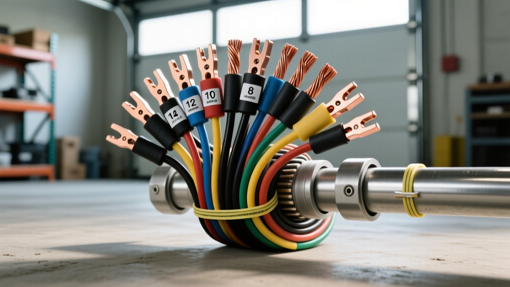
Defining the Amp Capacity of Wire Gauges in Automotive Systems
When designing, repairing, or upgrading vehicle electrical systems, understanding the amp capacity of wire gauges is the single most critical factor in preventing fires, voltage starvation, and component failure. Unlike residential alternating current (AC) wiring, automotive direct current (DC) systems operate at low voltages (typically 12V to 14.4V, or 24V to 28.8V in heavy-duty applications). Because power (Watts) equals voltage multiplied by current (Amps), a low-voltage system must draw significantly higher amperage to deliver the same wattage as a high-voltage system. Consequently, the ampacity limits of automotive wiring must be meticulously calculated to handle these heavy current loads without excessive resistive heating.
It is vital to distinguish between "chassis wiring" and "power transmission." Most published ampacity charts reference power transmission, which assumes wires are bundled tightly in conduit over long distances. Automotive wiring falls under "chassis wiring," where runs are short, and wires are often exposed to free air, allowing for higher safe ampacity limits. However, engine bay environments introduce extreme ambient heat, which severely derates these capacities.
SAE J1128 vs. Standard AWG: The Automotive Standard
The American Wire Gauge (AWG) system dictates the physical cross-sectional area of the conductor. However, in the automotive industry, bare AWG numbers are not enough. The SAE J1128 Low Tension Primary Cable Standard governs the insulation thickness, strand count, and temperature ratings for vehicle wiring. SAE J1128 specifies that automotive wire must use stranded copper to withstand the constant vibration and flexing of a vehicle chassis. Solid core wire, while common in household wiring, will quickly work-harden, fracture, and create high-resistance points under the hood of a car.
Furthermore, modern automotive wire utilizes Cross-Linked Polyethylene (XLPE) insulation—commonly designated as GXL, TXL, or SXL. This insulation allows for thinner wire walls compared to traditional PVC (Primary wire), meaning you can fit more copper into the same physical space, effectively increasing the amp capacity of wire gauges within tight connector housings like the Aptiv Metri-Pack series.
Comprehensive Automotive Amp Capacity of Wire Gauges Chart
The following reference table outlines the maximum safe ampacity for standard SAE J1128 stranded copper wire in a 12V/24V DC chassis wiring application. These ratings assume an ambient temperature of 85°C (185°F) or lower. If routing wire near exhaust manifolds or turbochargers where temperatures exceed 125°C, you must apply a 20% to 30% derating factor.
| AWG Size | Strand Count | Nominal OD (in) | Chassis Wiring Ampacity (Max) | Resistance per 1,000 ft (Ω) | Common Automotive Application |
|---|---|---|---|---|---|
| 18 AWG | 16 | 0.050 | 16 A | 6.385 | ECU sensor signals, LED marker lights, horn relay trigger |
| 16 AWG | 19 | 0.063 | 22 A | 4.016 | Fuel pump circuits, interior lighting, power antenna |
| 14 AWG | 19 | 0.073 | 32 A | 2.525 | Headlight high/low beams, horn power, cigarette lighter |
| 12 AWG | 19 | 0.094 | 41 A | 1.588 | Power windows, seat heaters, 40A relay feed circuits |
| 10 AWG | 19 | 0.116 | 55 A | 0.999 | Off-road light bars, radiator cooling fans, ABS modules |
| 8 AWG | 19 | 0.146 | 73 A | 0.628 | High-output alternator feeds, subwoofer amplifiers |
| 6 AWG | 19 | 0.184 | 101 A | 0.395 | Main battery to fuse block, heavy-duty winch relays |
| 4 AWG | 19 | 0.232 | 131 A | 0.248 | Starter motor feeds, EV battery interconnects |
| 2 AWG | 19 | 0.292 | 173 A | 0.156 | High-amp alternator upgrades (200A+), welding cable |
| 1/0 AWG | 19 | 0.368 | 233 A | 0.098 | Custom high-current bus bars, heavy equipment starters |
The Voltage Drop Factor: Why Ampacity Isn't the Only Metric
A wire might be capable of handling 55 Amps without melting (its thermal ampacity), but it may still fail to deliver adequate power to the component due to voltage drop. In a 12V system, a voltage drop greater than 3% (0.36V) across a circuit is generally considered unacceptable for sensitive electronics, while a 5% drop (0.6V) is the maximum tolerable limit for high-draw resistive loads like lighting or heating elements.
To calculate voltage drop, use the following formula:
Voltage Drop = (2 x L x I x R) / 1000
- L = Total length of the wire run in feet (positive AND ground paths combined)
- I = Current draw in Amps
- R = Resistance per 1,000 ft of the specific wire gauge
Real-World Scenario: You are wiring a 40 Amp off-road LED light bar mounted on the roof rack. The total wire run (from battery to relay, relay to lights, and ground back to chassis) is 30 feet. If you use 12 AWG wire (Resistance = 1.588 Ω/1000ft), the voltage drop is: (2 x 30 x 40 x 1.588) / 1000 = 3.81 Volts. Your light bar will only see 8.2 Volts, resulting in severe dimming and potential flickering. By stepping up to 8 AWG wire (Resistance = 0.628 Ω/1000ft), the drop falls to 1.5 Volts, which is still high. Using 4 AWG wire drops the loss to an acceptable 0.75 Volts, ensuring full luminosity.
Connector and Terminal Derating: The Hidden Bottleneck
A common mistake among amateur auto electricians is sizing the wire correctly but ignoring the terminal limitations. The amp capacity of wire gauges is entirely negated if the connector pins cannot handle the thermal load. According to Aptiv Metri-Pack Connector Series Specifications, the physical size of the terminal dictates the maximum continuous current:
- Metri-Pack 150 Series: Max 14 Amps (Typically uses 18-20 AWG wire)
- Metri-Pack 280 Series: Max 20 Amps (Typically uses 14-16 AWG wire)
- Metri-Pack 630 Series: Max 46 Amps (Typically uses 10-12 AWG wire)
- Weather-Pack Terminals: Max 20 Amps (Regardless of whether you crimp 12 AWG or 16 AWG into the barrel)
If you are wiring a 35 Amp cooling fan, using 10 AWG wire is correct, but you cannot use a standard Weather-Pack or Metri-Pack 280 connector. The terminal will overheat, melt the plastic housing, and cause a dead short. You must use a Metri-Pack 630, a Deutsch DT (rated for 13A per pin, so you'd need a dual-pin setup), or a heavy-duty ring terminal bolted directly to a relay bus bar.
High-Current Applications: Winches and EV Systems
When dealing with extreme amperage, standard SAE J1128 primary wire is often insufficient due to strand count and flexibility limitations. For a 12,000 lb automotive winch, the stall current can exceed 450 Amps. Standard 2 AWG battery cable will overheat rapidly during a sustained pull. Professionals use 4/0 AWG fine-strand welding cable for these applications. Welding cable features thousands of ultra-fine copper strands (often 30 AWG or smaller per strand), providing immense flexibility and a slightly higher copper-to-insulation ratio, which increases the effective amp capacity of the wire gauge under extreme transient loads.
In modern Electric Vehicles (EVs) and Hybrids, high-voltage (HV) cabling operates between 400V and 800V. While the voltage is high (meaning lower amperage for the same wattage), the ampacity requirements for the main traction battery cables still demand 2 AWG to 4/0 AWG shielding. EV high-voltage cables are universally jacketed in bright orange XLPE to warn first responders and technicians of lethal DC voltage. These cables feature an inner braided copper shield to prevent Electromagnetic Interference (EMI) from disrupting the vehicle's CAN bus networks, a factor that slightly reduces the thermal dissipation of the wire and requires careful routing away from sharp chassis edges.
Expert Troubleshooting: Signs of Undersized Wiring
If you are diagnosing an existing vehicle harness, look for these telltale signs that the amp capacity of the installed wire gauges has been exceeded:
- Brittle or Discolored Insulation: If the PVC or XLPE insulation feels hard to the touch, cracks when bent, or shows brown scorch marks near the crimp barrel, the wire has been subjected to thermal overload.
- Melted Relay Sockets: A melted ISO mini relay socket (specifically around Pin 30 and Pin 87) usually indicates that the wire gauge feeding the relay is too small, causing the terminal to act as a resistor and generate localized heat.
- Dimming Lights Under Load: If your headlights dim when the radiator fan engages, the ground wire for the fan circuit is likely undersized (e.g., using 16 AWG instead of 12 AWG), causing the current to seek an alternative ground path through the lighting circuit.
Always verify your circuits with a digital multimeter (DMM) under load. Testing voltage with the circuit off will not reveal voltage drop issues. For deeper diagnostic procedures and standardized testing methods, refer to the Engineering Toolbox AWG Wire Data and OEM-specific wiring schematics to ensure your repairs meet factory safety tolerances.