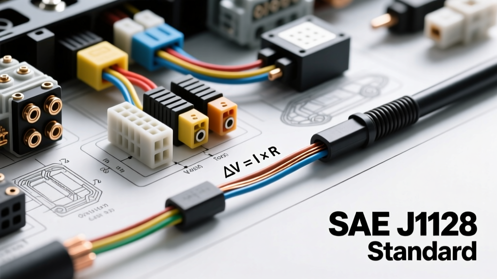
The Physics of Voltage Drop in 12V and 48V Systems
When upgrading an alternator for a high-output audio system, wiring an EV conversion, or installing a heavy-duty winch, guessing your American Wire Gauge (AWG) is a recipe for catastrophic failure. In a 12V automotive electrical system, current draw is significantly higher than in household AC systems for the same wattage. For example, a 2000W car audio amplifier pulls over 160 amps at 12.5V, whereas a 2000W household appliance pulls only 16.6 amps at 120V. This massive current volume turns undersized wiring into a literal heating element. Understanding how to determine wire gauge requires moving beyond basic ampacity charts and diving into the physics of voltage drop, circular mils, and thermal derating.
SAE J1128 vs. NEC: Why House Wire Fails in Vehicles
A common and dangerous mistake among novice fabricators is using solid-core or standard stranded copper wire rated for the National Electrical Code (NEC) in automotive applications. Automotive environments are subjected to extreme vibration, thermal cycling, and exposure to petroleum-based chemicals. Wire manufactured to SAE J1128 standards is specifically engineered for these conditions.
SAE J1128 defines several primary cable types used in high-current automotive applications:
- SGT (Standard): Features a thicker PVC insulation and a high strand count (e.g., 1 AWG SGT contains 224 strands of 26 AWG wire) for maximum flexibility. Rated for continuous use up to 105°C.
- SGX (Cross-Linked): Utilizes cross-linked polyethylene (XLPE) insulation. It is highly resistant to abrasion, battery acid, and extreme heat, carrying a 125°C rating. This is the gold standard for engine bay battery cables.
- TXL (Thin Wall): Offers the same 125°C rating as SGX but with thinner insulation, reducing weight and saving space in tight harness wraps, though it is less common for massive high-current battery runs.
Furthermore, SAE stranded wire utilizes a much finer stranding architecture than NEC building wire. This fine stranding increases the surface area of the copper, improving flexibility and resistance to work-hardening and breakage caused by chassis vibration.
The Core Formula: How to Determine Wire Gauge Mathematically
To accurately determine the correct AWG size, you must calculate the acceptable voltage drop across the entire circuit length. In automotive systems, a voltage drop of more than 0.2V to 0.3V on a high-current charging circuit is unacceptable, as it will prevent the battery from receiving the proper alternator output voltage.
Calculating Circular Mils (CM)
Instead of relying on generic charts, use the Circular Mil formula to find the exact cross-sectional area required for your specific run. The formula is:
CM = (2 × K × I × L) / E
- CM: Circular Mils (the cross-sectional area of the wire)
- K: Specific resistance of copper. Use 12.9 for copper at 75°C (a realistic operating temperature in an engine bay).
- I: Current in Amps
- L: One-way length of the wire in feet
- E: Acceptable voltage drop (e.g., 0.2V)
Real-World Calculation Example: 200A Alternator Upgrade
Imagine you are upgrading a 1999 GMC Sierra with a 200A alternator. The distance from the alternator output post to the main battery positive terminal is 9 feet. You want to limit the voltage drop to a strict 0.2V to ensure optimal ECU and fuel pump voltage.
CM = (2 × 12.9 × 200 × 9) / 0.2
CM = 46,440 / 0.2
CM = 232,200 Circular Mils
Looking at an AWG reference chart, 1/0 AWG has 105,600 CM, 2/0 AWG has 133,100 CM, 3/0 AWG has 167,800 CM, and 4/0 AWG has 211,600 CM. To meet the strict 0.2V drop requirement over 9 feet at 200A, you must step up to 250 kcmil (250,000 CM) wire. If you can tolerate a 0.3V drop, 4/0 AWG becomes mathematically sufficient. This mathematical approach is how professional marine and EV engineers size their primary bus bars and battery cables.
Temperature Derating in Engine Bays
Ampacity charts are typically based on an ambient temperature of 30°C (86°F). However, routing a battery cable near exhaust headers or above a transmission bell housing exposes the wire to ambient temperatures exceeding 80°C. According to Southwire automotive cable specifications, as ambient temperature rises, the wire's ability to dissipate heat generated by electrical resistance decreases. If your 1/0 AWG SGX cable is routed through a 60°C ambient zone, its ampacity must be derated by roughly 20%. Always route high-current positive cables along the vehicle's frame rails or inner fenders, avoiding the exhaust crossover and engine block whenever possible.
High-Current Automotive AWG Reference Chart
The following chart provides baseline AWG recommendations for common high-current automotive circuits, assuming a standard 12V system, a maximum 5-foot one-way run, and an ambient temperature of 30°C. Always adjust for longer runs using the CM formula above.
| Application | Peak Amp Draw | Continuous Amp Draw | Recommended AWG (SGX/SGT) | Overcurrent Protection |
|---|---|---|---|---|
| Starter Motor (V8 Gas) | 350A - 500A | 150A (cranking) | 1/0 AWG or 2/0 AWG | Fusible Link / Solenoid |
| High-Output Alternator | 150A - 250A | 120A - 200A | 1/0 AWG to 4/0 AWG | ANL or Class T Fuse |
| EV Battery Interconnects | 600A+ | 200A - 400A | 2/0 AWG to 500 kcmil | Class T / Pyro Fuse |
| 12,000 lb Winch | 400A - 450A | 300A (under load) | 2/0 AWG | Heavy Duty Solenoid |
| Car Audio Amplifier (Main) | 180A | 120A | 1/0 AWG | ANL Fuse (within 18' of battery) |
Termination, Crimping, and Real-World Failure Modes
Determining the correct wire gauge is only half the battle; improper termination will bottleneck the circuit and create a high-resistance point that melts connectors. When terminating 1/0 AWG or larger SGX wire, you must use closed-barrel, tinned copper lugs sized specifically for both the wire gauge and the stud size (e.g., a 2/0 AWG lug with a 3/8" stud hole for a standard Mega Fuse holder).
Never use hammer-style crimpers or pliers on high-current battery cables. These tools deform the copper strands unevenly, leaving air pockets inside the barrel. Moisture and battery acid will wick into these pockets via capillary action, causing green copper oxidation (verdigris) that drastically increases resistance. Instead, use a hydraulic hex-die crimper. The hex die compresses the copper lug and wire into a solid, cold-welded hexagonal mass, eliminating air gaps.
After crimping, seal the termination using dual-wall, adhesive-lined heat shrink tubing. As the tubing shrinks, the inner meltable adhesive layer flows into the wire strands, creating a waterproof, airtight seal that prevents acid wicking. For chassis grounds, always scrape away paint and clear coat down to bare, shiny metal, and apply a conductive anti-oxidant paste (like Noalox) to prevent galvanic corrosion between the copper lug and the steel chassis. Following these Painless Performance Wiring guidelines ensures that the wire gauge you calculated performs flawlessly in the real world.