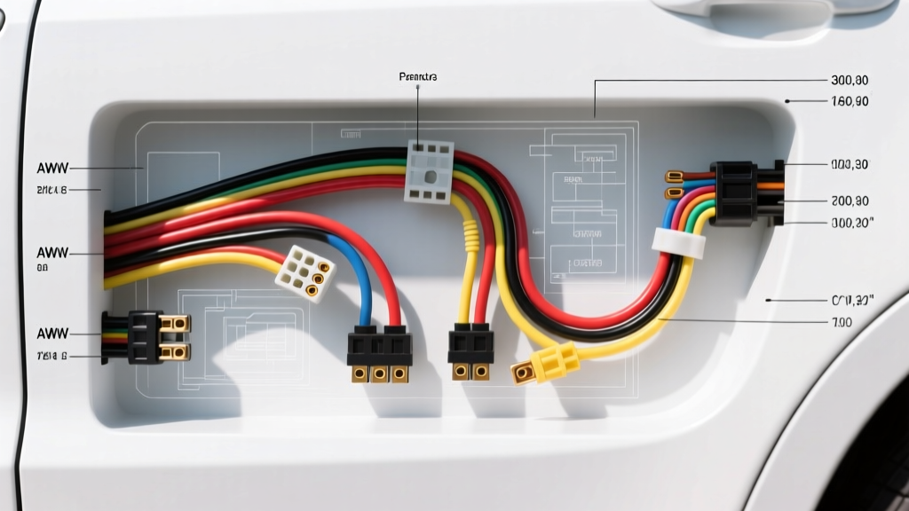
Amplifier Wire Gauge Specifications and Current Draw Dynamics
Selecting the correct amplifier wire gauge is the most critical step in any high-current automotive audio installation. Unlike low-current signal wiring, power and ground conductors for car audio amplifiers must handle massive transient current spikes and continuous high-amperage loads without inducing voltage drop or thermal runaway. Undersized power wire restricts current flow, forcing the amplifier's switching power supply to work harder, which generates excess heat, triggers thermal protection circuits, and introduces severe audio clipping.
This technical reference provides exact American Wire Gauge (AWG) specifications, current draw calculations, and material science comparisons between Oxygen-Free Copper (OFC) and Copper-Clad Aluminum (CCA) to ensure your electrical system operates at peak efficiency.
The Physics of Amplifier Current Draw
A common mistake in mobile electronics is sizing wire based on the amplifier's advertised 'Peak' or 'Max' wattage. Wire gauge must be calculated using the amplifier's continuous RMS wattage, the vehicle's charging system voltage, and the amplifier's topological efficiency.
To determine the exact maximum current draw ($I$) in Amperes, use the following electrical formula:
Formula: I = P / (V × η)
- P = Total RMS Wattage output
- V = System Voltage (14.4V with engine running, 12.0V with engine off)
- η = Amplifier Efficiency (Class D ≈ 0.80, Class AB ≈ 0.60)
Real-World Calculation Example:
A Class D monoblock amplifier rated at 1,500 Watts RMS. Assuming an 80% efficiency and a resting alternator voltage of 13.8V (a realistic real-world charging voltage, rather than the theoretical 14.4V):
I = 1500 / (13.8 × 0.80) = 135.8 Amps.
If the vehicle is idling and voltage drops to 12.5V, the current draw spikes to 150 Amps. This continuous load dictates the minimum required AWG size to prevent the wire from becoming a resistor.
Comprehensive Amplifier Wire Gauge Reference Chart
The following chart outlines the minimum recommended OFC (Oxygen-Free Copper) wire gauge based on total RMS system wattage and the physical distance from the battery positive terminal to the amplifier's power distribution block. These specifications adhere to the strict 0.5-volt maximum drop rule for high-fidelity 12V DC applications.
| Total RMS Wattage | Est. Max Current (Class D) | 0 - 10 ft Run (AWG) | 10 - 15 ft Run (AWG) | 15 - 20 ft Run (AWG) |
|---|---|---|---|---|
| Up to 300W | 30A | 8 AWG | 8 AWG | 4 AWG |
| 300W - 600W | 60A | 4 AWG | 4 AWG | 2 AWG |
| 600W - 1000W | 100A | 4 AWG | 2 AWG | 1/0 AWG |
| 1000W - 1500W | 150A | 1/0 AWG | 1/0 AWG | 2/0 AWG |
| 1500W - 2500W | 250A | 1/0 AWG | 2/0 AWG | 3/0 AWG |
| 2500W - 4000W+ | 400A+ | 2/0 AWG (Dual Run) | 3/0 AWG (Dual Run) | 4/0 AWG (Dual Run) |
Note: If utilizing Copper-Clad Aluminum (CCA) wire, you must increase the wire thickness by at least one to two AWG sizes (e.g., use 1/0 AWG CCA where 4 AWG OFC is specified) due to the higher resistivity of aluminum.
Material Science: OFC vs. CCA Conductors
The automotive electrical environment is harsh, subject to extreme temperature fluctuations, vibration, and corrosive elements. The metallurgical composition of your amplifier wire gauge directly impacts system longevity and performance.
Oxygen-Free Copper (OFC)
OFC is the industry standard for high-current automotive applications. It contains less than 0.001% oxygen, which prevents copper oxide formation within the strand matrix. According to data referenced by the Engineering Toolbox AWG Resistance Data, pure copper maintains a highly predictable resistance curve and excellent thermal dissipation properties. OFC wire is highly flexible, resisting strand breakage when routed through tight firewall grommets and under carpeting.
Copper-Clad Aluminum (CCA)
CCA wire features an aluminum core with a thin electroplated copper exterior. While it is cheaper and lighter, aluminum has roughly 61% of the conductivity of copper. Consequently, a 4 AWG CCA wire has the equivalent DC resistance of a 6 AWG OFC wire. Furthermore, when the outer copper layer is nicked during stripping or crimping, the exposed aluminum rapidly oxidizes when exposed to atmospheric moisture, leading to increased contact resistance and potential fire hazards at the terminal connections. For high-power subwoofer amplifiers exceeding 1000W RMS, CCA is strongly discouraged.
AWG Resistance and Ampacity Specifications
Understanding the exact resistance per 1,000 feet of conductor allows installers to calculate precise voltage drop. The SAE J1127 Battery Cable Standard outlines the stringent requirements for high-strand-count copper cables used in automotive starter and battery applications, which serves as the benchmark for premium car audio power wire.
| AWG Size | Strand Count (Fine) | Diameter (Inches) | Resistance (Ω / 1000 ft) | Max Ampacity (12V DC Auto) |
|---|---|---|---|---|
| 4 AWG | 1666 | 0.2043 | 0.2485 | 95A |
| 2 AWG | 2646 | 0.2576 | 0.1563 | 125A |
| 1/0 AWG | 4186 | 0.3249 | 0.0983 | 150A |
| 2/0 AWG | 5292 | 0.3648 | 0.0618 | 195A |
| 4/0 AWG | 8400 | 0.4600 | 0.0390 | 260A |
Grounding Architecture and Chassis Preparation
The ground wire is not merely a return path; it is the reference voltage baseline for the amplifier's internal switching power supply and audio op-amps. A poor ground introduces ground loop alternator whine and restricts current flow just as severely as an undersized power wire.
Technical Grounding Procedure:
- Wire Sizing: The ground wire must be the exact same AWG and material as the main power wire. Never use a smaller gauge for the ground return.
- Chassis Preparation: Locate a structural, unpainted steel point on the vehicle's chassis or seatbelt tower. Use a rotary tool with a brass wire brush or 60-grit sandpaper to remove all paint, clear coat, and primer down to bare, shiny metal. The contact area must be slightly larger than the ring terminal footprint.
- Chemical Treatment: Apply a conductive anti-oxidant paste (such as No-Ox-Id A-Special) to the bare metal and the inside of the crimped ring terminal. This prevents galvanic corrosion and moisture ingress.
- Hardware and Torque: Use a Grade 8 or Stainless Steel M8 or M10 hex bolt with a split lock washer and a flat washer. Torque the bolt to the vehicle manufacturer's specification (typically 15-22 ft-lbs for M8 structural bolts) to ensure maximum surface area contact and vibration resistance.
Overcurrent Protection: Fusing the Amplifier Circuit
The primary fuse located within 18 inches of the battery positive terminal is designed to protect the wire, not the amplifier. If the power wire chafes against the firewall and shorts to the chassis, the fuse must blow before the wire melts and ignites the vehicle's interior.
Therefore, the main fuse rating must be equal to or slightly less than the maximum ampacity of the selected wire gauge, while remaining at least 125% of the amplifier's maximum calculated current draw. For installations utilizing 1/0 AWG OFC wire (rated for 150A), a 150A ANL fuse is appropriate. For systems drawing over 250A, standard ANL fuses may suffer from fatigue and voltage drop; upgrade to T-Class (Class T) fuses, which offer superior interrupting capacity (up to 20,000 Amps) and handle high transient inrush currents without nuisance blowing.
Summary and Best Practices
Proper amplifier wire gauge selection bridges the gap between theoretical amplifier output and real-world acoustic performance. By calculating true RMS current draw, utilizing high-strand-count OFC conductors, adhering to strict chassis grounding protocols, and sizing overcurrent protection based on wire ampacity, you ensure a mobile audio system that is safe, reliable, and capable of delivering uncompromised transient response. For further installation methodologies and vehicle-specific wiring integration, consult the Crutchfield Car Audio Wiring Guide for model-year-specific harness adapters and integration schematics.