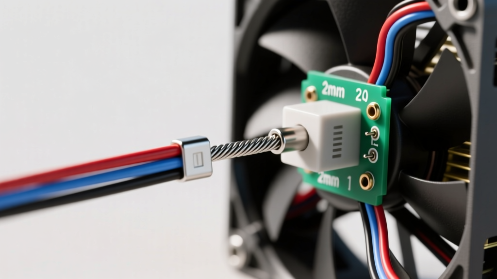
Understanding Metric 2mm² vs. 14 AWG in Automotive Harnesses
When navigating modern automotive wiring diagrams, particularly in European vehicles or high-end aftermarket ECU installations, you will frequently encounter the 2mm wire gauge specification. It is critical to understand that in metric automotive wiring, "2mm" refers to the cross-sectional area of the copper conductor (2mm²), not the diameter. A 2mm² cross-sectional area is the functional and physical equivalent of 14 AWG (American Wire Gauge).
According to SAE J1128 standards for Low Tension Primary Cable, a standard 2mm² (14 AWG) automotive wire features 19 strands of 0.38mm bare copper. This stranding configuration provides the necessary flexibility to withstand engine bay vibrations while maintaining a maximum resistance of approximately 0.0094 ohms per meter (or 2.87 ohms per 1,000 feet) at 20°C. Selecting the correct 2mm² wire type—typically TXL (thin-wall, 125°C) or GXL (general-purpose, 125°C)—is vital for ensuring the insulation does not melt near exhaust manifolds or high-heat cylinder heads.
Complete Wiring Diagram Walkthrough: ECU-Controlled Cooling Fan
To demonstrate the practical application of the 2mm wire gauge, we will walk through a complete wiring diagram for an ECU-controlled electric cooling fan circuit. This setup is ubiquitous in GM LS engine swaps and modern aftermarket EFI systems like the Holley Terminator X. The circuit utilizes a standard Bosch-style ISO Mini Relay to switch high amperage to the fan motor, while relying on 2mm² wire for the low-current control side.
Step 1: The Ignition Feed (Relay Pin 86)
The relay coil requires a 12V reference to energize. We route an ignition-switched 12V source from the fuse block to Relay Pin 86.
- Wire Gauge: 2mm² (14 AWG)
- Insulation Color: Pink (GM standard for ignition-switched 12V)
- Protection: 10A ATO Fuse
Step 2: The ECU Switched Ground (Relay Pin 85)
The ECU triggers the fan by completing the ground path for the relay coil. The wire runs from Relay Pin 85 directly to the ECU's low-side driver output (e.g., Holley Terminator X Pin A14 or GM ECU Pin 24).
- Wire Gauge: 2mm² (14 AWG)
- Insulation Color: Dark Green with White Stripe (Typical ECU control ground)
- Connector: Deutsch DT Size 16 Pin or ECU-specific Weather-Pack terminal
Step 3: High-Current Switched Output (Pins 30 and 87)
While the control circuit relies on the 2mm wire gauge, the load circuit demands heavier copper. Pin 30 receives direct battery power via a 30A fuse using 10 AWG (6mm²) wire. Pin 87 routes the switched 12V to the cooling fan motor, also utilizing 10 AWG wire to handle the 15A-25A inrush current of the fan motor without excessive voltage drop.
2mm² Automotive Wire Technical Specifications Chart
| Specification | Metric (2mm²) | Imperial Equivalent (14 AWG) |
|---|---|---|
| Cross-Sectional Area | 2.00 mm² | 2.08 mm² |
| Conductor Diameter (Nominal) | 1.60 mm | 1.63 mm |
| Standard Stranding (SAE J1128) | 19 / 0.38 mm | 19 / 0.38 mm |
| Max Resistance @ 20°C | 9.4 Ω / km | 2.87 Ω / 1000 ft |
| Continuous Ampacity (125°C TXL) | ~18 Amps | ~18 Amps |
| Recommended Crimp Cavity | 1.5 - 2.5 mm² | 16-14 AWG (Blue/Deutsch Sz 16) |
Connector Selection and Crimping Protocols
When terminating 2mm² wire, the choice of connector and crimp tool is just as critical as the wire gauge itself. For under-hood applications exposed to moisture and vibration, sealed connectors are mandatory.
- Deutsch DT Series: Use Size 16 solid contacts (part number 0460-202-1631). The crimp barrel is specifically designed for 14-16 AWG (1.5mm² to 2.5mm²) wire. Ensure the wire insulation sits flush with the inspection hole of the contact barrel.
- GM Weather-Pack: Use the 14-16 AWG male/female terminals. The crimp wings must securely fold over the 19 strands of the 2mm² wire without cutting into the copper.
- Crimp Tooling: Always use a ratcheting crimp tool calibrated for the specific terminal. A non-ratcheting tool can lead to under-crimping, which increases contact resistance and causes the terminal to overheat, melting the connector housing.
Voltage Drop Calculations for Long Harness Runs
One of the primary reasons engineers specify the 2mm wire gauge for ECU control circuits is to mitigate voltage drop. Let's calculate the voltage drop for a 4-meter total run (2 meters to the ECU, 2 meters back) of 2mm² wire carrying a 200mA (0.2A) relay coil current.
Formula: V_drop = Current × Resistance
Resistance of 4m of 2mm² wire: 4m × 0.0094 Ω/m = 0.0376 Ω
Voltage Drop: 0.2A × 0.0376 Ω = 0.00752 Volts
A voltage drop of less than 0.01V is negligible, ensuring the ECU sees a near-perfect ground reference. If 20 AWG (0.5mm²) wire were used, the resistance would jump to roughly 0.14 Ω, resulting in a 0.028V drop. While still small, the mechanical fragility of 20 AWG wire in an engine bay makes 2mm² the undisputed choice for reliability. For detailed relay coil resistance and flyback voltage specifications, refer to the Littelfuse Automotive Mini-Relay Datasheet.
Real-World Troubleshooting & Failure Modes
When diagnosing a cooling fan circuit that utilizes 2mm² control wiring, technicians should look for the following specific failure modes:
- Firewall Grommet Chafing: The 2mm² Dark Green/White wire passing through the firewall is highly susceptible to chafing against sharp sheet metal. If the TXL insulation wears through, the ECU will detect a short to ground and immediately shut down the low-side driver to protect itself, resulting in a fan that never turns on and an overheating engine.
- Flyback Voltage Spikes: If the 2mm² wire is repaired using a cheap twist-and-tape method rather than a soldered heat-shrink splice, the added resistance can interfere with the relay's internal suppression diode. This allows inductive flyback voltage spikes (often exceeding 60V) to travel back to the ECU, permanently frying the microprocessor's output pin.
- Corrosion at Pin 85: If the relay is mounted in an unsealed bracket, capillary action can draw moisture down the 2mm² wire strands into the crimp barrel. This creates copper oxide, increasing resistance. Perform a voltage drop test across the 2mm² wire while the relay is energized; any reading above 0.1V indicates corrosion or a failing crimp.