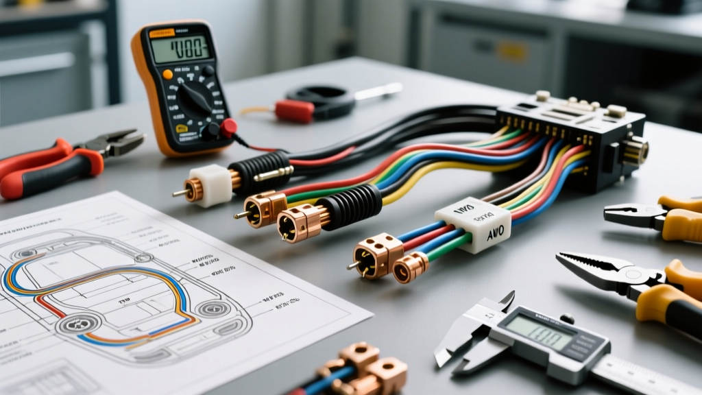
The True Cost of Miscalculating Automotive Wire Gauge
When modifying a vehicle’s electrical system—whether installing a high-output alternator, upgrading fuel pumps for forced induction, or wiring a winch—knowing how to calculate wire gauge is the foundational step. However, most online guides focus solely on the physics of voltage drop and ampacity, ignoring a critical real-world factor: the financial and tooling implications of your gauge selection.
Over-gauging a circuit wastes significant capital and necessitates expensive, heavy-duty termination tools. For example, running 1/0 AWG battery cable for a 30A fuel pump circuit is not just overkill; it requires purchasing heavy-gauge ring terminals (which cost 400% more than standard sizes) and a hydraulic or heavy-ratchet crimper that can exceed $150. Conversely, under-gauging a circuit leads to catastrophic voltage drop. A 2-volt drop across a fuel pump wire will starve the injectors, lean out the air/fuel ratio under boost, and ultimately melt the wire insulation, potentially causing an engine bay fire.
This analysis breaks down the exact costs, tooling requirements, and calculation methodologies needed to execute professional-grade automotive wiring without blowing your budget on unnecessary copper or inadequate tooling.
Essential Tools Required to Calculate and Verify Wire Gauge
Accurately calculating wire gauge requires more than a basic online calculator. You must account for the specific thermal properties of automotive wire (like GXL or TXL cross-linked polyethylene) and verify your calculations in the real world. Here is the required tooling ecosystem and its associated costs.
Digital Multimeters and Voltage Drop Testing
To verify that your calculated wire gauge is performing correctly under load, you must perform a live voltage drop test. This requires a Digital Multimeter (DMM) with millivolt (mV) resolution and a fast sampling rate.
- Entry-Level: Innova 5610 Automotive DMM (~$150). Offers basic millivolt resolution and duty cycle measurements, sufficient for basic 12V accessory circuits.
- Professional: Fluke 87V Industrial Multimeter (~$450). The industry standard for its 0.1mV resolution and low-pass filter, allowing you to measure voltage drop across a single wire while an AC compressor clutch or PWM cooling fan cycles.
Precision Wire Strippers and Crimpers by AWG
The gauge you calculate dictates the termination tools you must buy. Standard automatic wire strippers often fail on 8 AWG and larger GXL (thin-wall) wire, nicking the copper strands. Nicking just three strands on a 10 AWG wire effectively reduces its cross-sectional area to 12 AWG, creating a localized high-resistance hotspot.
- 16 to 10 AWG: Standard ratcheting crimpers (e.g., IWISS or Glarks) cost between $30 and $50. These handle standard insulated and non-insulated terminals.
- 8 to 4 AWG: Requires a heavy-duty ratcheting crimper with hexagonal or indenter dies (e.g., Titan or Knoweasy). Expect to spend $60 to $110. These are mandatory for achieving a gas-tight crimp on high-current circuits.
- 2 AWG to 1/0 AWG: Requires a large mechanical ratchet or a 12-ton hydraulic crimping tool ($120 to $250). Hand-crimping 1/0 AWG with pliers is a severe safety hazard that guarantees high resistance and eventual thermal failure.
Cost Analysis: AWG Sizing and Tooling Requirements
The following table illustrates the compounding costs of selecting different wire gauges for a standard 10-foot automotive run. Notice how the cost of terminals and tooling scales exponentially as the wire gauge increases.
| AWG Size | Copper Cost (10 ft) | Terminal Cost (Pair) | Crimper Required | Tooling Cost | Total Project Cost |
|---|---|---|---|---|---|
| 10 AWG | $8.50 | $1.50 | Standard Ratchet | $35.00 | $45.00 |
| 8 AWG | $14.00 | $3.00 | Heavy Ratchet | $75.00 | $92.00 |
| 4 AWG | $32.00 | $8.00 | Large Mechanical | $110.00 | $150.00 |
| 1/0 AWG | $65.00 | $14.00 | Hydraulic Press | $180.00 | $259.00 |
Note: Costs are estimated based on high-quality, bare-copper, marine-grade tinned terminals and GXL automotive wire. Using cheap CCA (Copper Clad Aluminum) wire will lower material costs but requires upsizing the gauge by at least one step due to higher resistance.
Real-World Application: Calculating Gauge for a 140A Alternator Upgrade
Let’s apply the math to a common automotive scenario: upgrading a factory 90A alternator to a 140A unit (common in LS swaps or high-draw audio systems). The distance from the alternator B+ terminal to the positive battery post is 5 feet. Therefore, the total round-trip circuit length (L) is 10 feet.
Step-by-Step Calculation and Cost Breakdown
We use the standard Circular Mil (CM) formula to calculate wire gauge, targeting a maximum voltage drop (VD) of 0.2V to ensure the battery receives a proper 14.2V+ charging voltage.
The Formula: CM = (K × I × L) / VD
- K (Resistance Constant): 10.77 for copper wire at standard engine bay temperatures (75°C).
- I (Current): 120A. (While the alternator is rated for 140A, continuous maximum draw should be calculated at 85% capacity for safety and thermal derating).
- L (Length): 10 feet (round trip).
- VD (Voltage Drop): 0.2V maximum allowable drop.
The Math: CM = (10.77 × 120 × 10) / 0.2
CM = 12,924 / 0.2
CM = 64,620 Circular Mils.
Consulting an AWG specification chart, we see that 2 AWG wire has a cross-sectional area of 66,360 CM. Therefore, 2 AWG GXL wire is the mathematically correct choice for this application.
Termination and Routing Specifics
For this 2 AWG run, you will need to purchase specific terminals. The alternator B+ post typically requires a 5/16-inch ring terminal, while the battery side requires a 3/8-inch or top-post clamp terminal. You must use bare copper terminals sealed with dual-wall, polyolefin heat shrink tubing (3:1 shrink ratio) containing an internal adhesive sealant. This prevents moisture ingress and corrosion, which is the leading cause of high-resistance failures in charging circuits.
Common Failure Modes from Improper Gauge Selection
Even if you correctly calculate wire gauge, poor execution and improper material selection will negate your math. As an automotive electrical diagnostic standard, voltage drop testing frequently reveals the following failure modes in aftermarket wiring:
1. Thermal Melting of PVC Insulated Terminals
Many DIYers use standard vinyl or nylon-insulated crimp terminals. These materials begin to soften and melt at 105°C. In an engine bay, near exhaust manifolds or turbochargers, ambient temperatures easily exceed this. Always use bare copper terminals with high-temperature heat shrink, or bare metal-to-metal crimps on high-amperage circuits, as the wire insulation itself (GXL or SXL) is rated for 125°C to 150°C.
2. 'Crimp Creep' from Non-Ratcheting Tools
Using cheap, non-ratcheting plier-style crimpers on 8 AWG or larger wire results in 'crimp creep.' Because the tool does not apply uniform, calibrated pressure, the copper strands are not fully compressed. Under heavy electrical load and engine vibration, the wire slowly works its way out of the terminal barrel. This creates an air gap, leading to severe arcing, localized melting, and eventual total circuit failure.
3. Ignoring Thermal Derating
Wire ampacity charts are typically based on a 60°C ambient environment. Under the hood of a vehicle, ambient temperatures routinely hit 100°C. According to SAE J1128 standards for automotive wire, you must derate the ampacity of the wire by 20% to 30% when routing through high-heat zones. If your calculation puts you on the absolute edge between 8 AWG and 6 AWG, always step up to the heavier gauge to account for engine bay thermals.
Summary
Knowing how to calculate wire gauge is only half the battle. By understanding the compounding costs of copper, heavy-duty terminals, and specialized crimping tools, you can budget accurately for your automotive electrical projects. Always verify your mathematical calculations with real-world millivolt voltage drop testing, and never compromise on ratcheting termination tools or high-temperature GXL wire insulation.