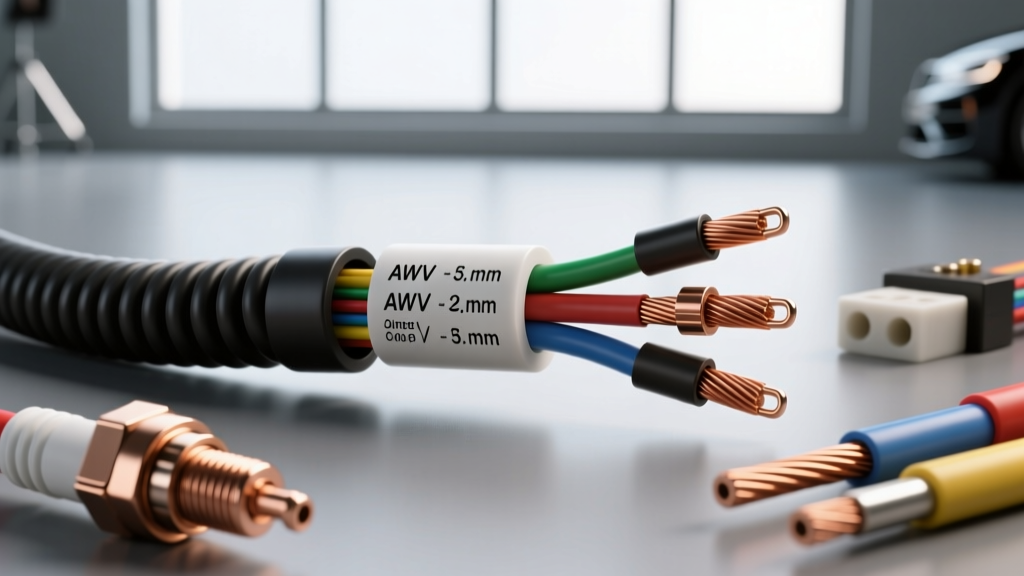
The 'Spark Plug Gauge Wire' Confusion: Diameter vs. AWG
When enthusiasts and technicians search for 'spark plug gauge wire,' they are usually colliding two entirely different electrical measurement systems. In the automotive world, traditional spark plug wires (the secondary high-voltage cables running from the distributor or coil pack to the spark plug) are measured by their outer insulation diameter in millimeters (mm)—typically 7mm, 8mm, 8.5mm, or 10mm. Conversely, the primary low-voltage wiring that feeds the ignition coils is measured using the American Wire Gauge (AWG) system.
Confusing these two metrics is a common pitfall that leads to severe engine performance issues, electrical fires, or catastrophic ECU damage. Understanding the distinction between secondary spark plug wire diameter and primary ignition harness AWG is critical for safe, reliable engine management. This guide breaks down the most dangerous mistakes made when sizing, selecting, and routing ignition wiring.
Mistake #1: Undersizing Coil-on-Plug (COP) Power Feeds
The most frequent 'gauge' mistake on modern engines involves the primary wiring harness feeding Coil-on-Plug (COP) ignition systems. Modern smart coils, such as those found on GM LS2/LS3 engines or Ford Modular V8s, are essentially individual transformers with built-in igniters. During the dwell phase, a single COP can draw between 8 and 14 amps of continuous current.
The Mistake: Builders often use 18 AWG or 20 AWG wire for custom COP harnesses because it is flexible and easy to route through tight engine bays. However, 18 AWG wire is only rated for roughly 5-7 amps in a high-heat chassis environment.
The Consequence: Using undersized wire creates significant voltage drop. If your alternator is outputting 14.2V, an undersized 18 AWG harness might deliver only 11.5V to the coil under heavy load (like wide-open throttle). This reduces the coil's dwell time, resulting in a weak spark, high-RPM misfires, and eventually, melted wiring or fried internal coil drivers.
The Fix: Always use a minimum of 14 AWG wire for the main 12V power feed to your ignition coils, and 16 AWG for the dedicated coil grounds. For reference, a standard Bosch or Denso 4-pin COP connector utilizes the following pinout:
- Pin 1: Ground (Requires 16 AWG, tied directly to engine block ground stud)
- Pin 2: ECU Trigger/Signal (20 AWG is sufficient, as this carries minimal current)
- Pin 3: Shield/Drain Wire (Tied to sensor ground at ECU)
- Pin 4: 12V Switched Power (Requires 14 AWG, fed via a dedicated 30A relay)
For specific vehicle applications, such as the Ford 4.6L 3-Valve, the OEM COP power wire is typically White with a Red tracer (14 AWG), while the ground is Black with a White tracer (16 AWG). Never substitute these with thinner gauges.
Mistake #2: Solid Core Plug Wires on OBD-II Vehicles
If your search for 'spark plug gauge wire' was actually regarding the secondary spark plug cables (measured in mm), the most dangerous mistake is selecting the wrong internal core material for your engine management system.
The Mistake: Installing solid copper or solid stainless steel core spark plug wires on any vehicle equipped with an ECU, electronic fuel injection (EFI), or OBD-II diagnostics. Solid core wires offer virtually zero electrical resistance (often less than 50 ohms per foot). While this sounds great for maximum spark energy, it acts as a massive antenna for Radio Frequency Interference (RFI) and Electromagnetic Interference (EMI).
The Consequence: The unfiltered EMI radiates through the engine bay and scrambles low-voltage sensor signals. This frequently causes erratic crankshaft position sensor readings, phantom O2 sensor codes, and erratic idle air control behavior. According to SAE Standard J2031 regarding high-tension ignition cables, modern vehicles require suppression-type wiring to protect onboard electronics.
The Fix: Always use spiral-wound (metallic core) or carbon-impregnated (non-metallic core) spark plug wires. Spiral-wound wires, such as those from MSD or Taylor, provide extremely low resistance (typically 40-50 ohms per foot) while the opposing spiral wrap cancels out EMI. For standard street applications, 8mm or 8.5mm diameter spiral core wires provide the optimal balance of dielectric insulation and EMI suppression.
Safety Warning: Dielectric Breakdown and Arcing Hazards
Secondary spark plug wires carry anywhere from 15,000 to over 45,000 volts depending on cylinder pressure and spark plug gap. A critical safety mistake is routing these high-voltage cables too close to exhaust headers or sharp metal brackets.
If an 8mm spark plug wire is resting against a 1,200°F exhaust manifold, the silicone or EPDM outer jacket will eventually bake, crack, and lose its dielectric strength. Once the insulation compromises, the 40,000V secondary charge will arc directly to the exhaust header. This not only causes a dead cylinder misfire but can ignite oil vapors or fuel leaks in the engine bay. Always maintain a minimum 2-inch clearance between spark plug wires and exhaust components, and use high-temp fiberglass wire looms or ceramic boot protectors when tight routing is unavoidable.
Reference Chart: Ignition Wire Specifications & Sizing
| Component | Measurement Type | Recommended Spec / Gauge | Max Resistance / Notes |
|---|---|---|---|
| COP Main 12V Power Feed | AWG (Primary) | 14 AWG (Stranded Copper) | < 2.5 Ohms per 1,000 ft |
| COP Dedicated Ground | AWG (Primary) | 16 AWG (Stranded Copper) | < 4.0 Ohms per 1,000 ft |
| COP ECU Trigger Signal | AWG (Primary) | 20 AWG (Shielded) | Use shielded cable to prevent cross-talk |
| Secondary Spark Plug Wire | Diameter (mm) | 8.0mm to 8.5mm | Spiral Core: 40-50 Ohms/ft (Per MSD Tech Notes) |
| Spark Plug Wire Boots | Material | High-Temp Silicone | Must withstand > 500°F continuous |
Troubleshooting Ignition Voltage Drop
If you suspect your primary ignition wiring gauge is insufficient, perform a loaded voltage drop test. You cannot test for voltage drop with the key off; the circuit must be under load (cranking or running).
- Prepare the Multimeter: Set your digital multimeter to DC Volts.
- Test the Power Side: Place the red probe directly on the positive battery terminal and the black probe on Pin 4 (12V Power) of the COP connector (back-pierced or using a breakout box).
- Crank the Engine: Have an assistant crank the engine. A healthy 14 AWG power feed should show a voltage drop of less than 0.2V. If you read 0.5V or higher, your wire gauge is too thin, or you have high resistance at a crimp terminal.
- Test the Ground Side: Place the red probe on Pin 1 (Ground) of the COP connector and the black probe directly on the negative battery terminal.
- Crank the Engine: The ground side voltage drop must also be less than 0.2V. If it is higher, upgrade your ground wire to 14 AWG and ensure the ring terminal is secured to a clean, bare-metal engine block grounding point, torqued to the manufacturer's specification (typically 15-20 lb-ft for M8 ground studs).
For further diagnostic procedures on ignition systems and wiring standards, refer to the NGK Technical Articles Library, which provides excellent visual guides on spark plug and coil testing. Never compromise on wire gauge in high-current ignition circuits; the cost of 14 AWG copper is negligible compared to the cost of replacing a set of fried smart coils or an engine control module.