Introduction: The 60-Amp Automotive Challenge
When building high-amperage automotive circuits—such as dual-battery isolators, 3000W power inverters, EV conversion charging ports, or heavy-duty off-road winch relays—the most common question we receive is: what gauge wire for 60 amp applications? The answer is not a simple single number. In automotive electrical systems, wire gauge selection depends heavily on the SAE J1128 standard, ambient engine bay temperatures, and the total length of the wire run.
The Core Answer: What Gauge Wire for 60 Amp Loads?
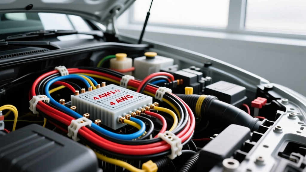
For a 60-amp continuous load in an automotive environment, 6 AWG wire is the absolute minimum requirement, but 4 AWG wire is the professional standard for most vehicle installations.
Many DIYers mistakenly reference the National Electrical Code (NEC) charts used for household wiring. However, automotive wiring must adhere to SAE J1128 specifications. Automotive wire (GXL, TXL, or SXL) features thinner insulation but higher temperature ratings (up to 155°C for SXL) compared to standard copper THHN. Furthermore, engine bays regularly see ambient temperatures exceeding 120°F (49°C), which severely degrades the ampacity of copper conductors. A 6 AWG SXL wire is rated for roughly 75 amps in a free-air, 77°F environment, but that rating drops to nearly 53 amps when bundled in a harness at 122°F. Therefore, upsizing to 4 AWG provides the necessary thermal headroom.
Voltage Drop: The Hidden 60-Amp Killer
Ampacity is only half the equation. Voltage drop is the primary reason professional auto electricians default to 4 AWG for 60-amp circuits. If you are running a 60-amp inverter to power a laptop and diagnostic tools in an overland rig, a voltage drop of more than 3% (0.36V on a 12V system) can trigger low-voltage shutdowns or cause sensitive ECU modules to reset.
| Wire Length (One Way) | 6 AWG Voltage Drop | 4 AWG Voltage Drop | Recommendation |
|---|---|---|---|
| 5 Feet | 0.12V (1.0%) | 0.07V (0.6%) | 6 AWG is acceptable |
| 10 Feet | 0.24V (2.0%) | 0.15V (1.2%) | 4 AWG recommended |
| 15 Feet | 0.36V (3.0%) | 0.22V (1.8%) | 4 AWG required |
| 20+ Feet | 0.48V (4.0%) | 0.30V (2.5%) | 4 AWG or 2 AWG required |
As noted by Blue Sea Systems circuit engineering guidelines, calculating the total circuit length means measuring from the battery positive post, to the load, and back to the chassis ground. Always measure the round-trip distance when using standard voltage drop calculators.
Step-by-Step 60-Amp Wiring Installation Guide
Knowing what gauge wire for 60 amp circuits is only the beginning. Proper termination and routing dictate whether your system will survive the harsh vibrations and thermal cycles of a vehicle chassis.
Step 1: Selecting the Correct Wire and Terminals
Purchase pure copper, tinned SXL or GXL wire. Avoid Copper Clad Aluminum (CCA) wire sold on discount marketplaces; CCA has higher resistance and is prone to galvanic corrosion when crimped to copper lugs. For 60-amp terminations, use closed-barrel, tinned copper ring terminals sized for 4 or 6 AWG. The stud hole should match your battery terminal or busbar exactly—typically 5/16-inch or 3/8-inch (M8/M10). Never use a larger ring terminal and make it fit by bending the lug, as this reduces the contact surface area and creates a high-resistance hot spot.
Step 2: Precision Stripping and Hex-Indent Crimping
Strip the SXL insulation using a specialized wire stripper that will not nick the outer strands of the copper bundle. A nicked strand creates a stress riser that will eventually snap under engine vibration. Insert the wire fully into the closed-barrel terminal until the copper is flush with the inspection window. Use a hex-indent crimper with the correct die for 4 or 6 AWG. The hex crimp cold-welds the copper strands and the terminal barrel together. Perform a pull test: a properly crimped 4 AWG terminal should withstand over 150 lbs of pull force before the wire yields.
Step 3: Adhesive Heat Shrink Sealing
Automotive environments are hostile. Road salt, moisture, and battery acid will wick into unsealed crimps via capillary action, turning the copper black and increasing resistance. Slide a piece of 3:1 ratio, dual-wall adhesive-lined heat shrink over the terminal before crimping. After crimping, position the heat shrink so it covers the barrel and extends 1/2-inch over the wire insulation. Apply heat starting from the center and moving outward. You must see the adhesive melt and squeeze out of the edges, creating a watertight environmental seal.
Step 4: Overcurrent Protection and Routing
Every 60-amp circuit requires a dedicated overcurrent protection device (OCPD). Install a 60-Amp ANL or Class-T fuse within 18 inches of the battery positive terminal. If the wire chafes against the firewall before the fuse, a dead short can weld the wire to the chassis and start a fire. Route the 4 AWG wire through the firewall using a dedicated rubber grommet. Secure the wire every 12 inches using UV-resistant nylon cable ties or stainless steel P-clamps lined with EPDM rubber to prevent insulation abrasion.
Upgrading the Alternator Ground Strap
A frequently overlooked aspect of installing high-amperage 60-amp circuits is the vehicle return path. If you are pulling 60 amps from a secondary battery or a high-output alternator, that current must return to the source. Factory alternator ground straps are often braided 10 AWG or 8 AWG wires, which are entirely insufficient for sustained 60-amp loads combined with standard vehicle charging currents. If the return path has high resistance, the alternator internal voltage regulator will overcompensate, leading to overvoltage conditions that can fry sensitive CAN-bus modules. Always upgrade the engine-to-chassis and engine-to-battery negative ground straps to 4 AWG flexible welding cable when adding continuous 60-amp loads to the system.
Torquing and Final Connection
When attaching the ring terminal to a busbar, battery post, or winch solenoid, the hardware matters. Use a Grade 8 or stainless steel flange nut. The torque specification for an M8 (5/16) terminal connection is typically 10 to 12 Nm (89 to 106 in-lbs). Under-torquing leads to micro-arcing and melted lugs; over-torquing can strip the threads or crack the copper lug. Apply a thin layer of dielectric grease or Noalox anti-oxidant compound to the mating surfaces before final tightening to prevent galvanic corrosion.
Common 60-Amp Wiring Failure Modes
- Melted Ring Terminals: Caused by loose connections (low torque) or using open-barrel crimps that vibrate loose over time. The high resistance generates intense localized heat.
- ECU Resetting Under Load: Caused by using 6 AWG wire on a 15-foot run. The voltage drop starves the ECU of minimum operating voltage when the 60-amp inverter kicks on.
- Parasitic Drain and Corrosion: Caused by failing to use adhesive-lined heat shrink. Moisture enters the crimp, oxidizes the copper, and creates a slow short to the chassis ground.
By selecting 4 AWG SXL wire, utilizing hex-indent crimps, and adhering to strict routing and fusing protocols, your 60-amp automotive circuit will deliver reliable, safe power for the life of the vehicle. For further reading on automotive wiring best practices, consult the Haynes automotive wiring tutorials to ensure your specific vehicle grounding topology can handle the return current.