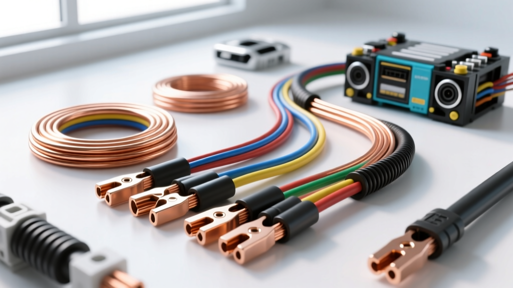
Introduction to 8 AWG in Automotive Applications
When upgrading a high-output alternator, wiring a Class D car audio amplifier, or routing power to an EV battery management system (BMS), understanding the true 8 gauge wire amp rating is critical. Many hobbyists and even some technicians rely on generic household wiring charts that fail to account for the harsh under-hood temperatures, continuous versus peak current draws, and voltage drop tolerances inherent to 12V and 48V automotive environments. Selecting the wrong wire material or insulation type can lead to catastrophic failure modes, including melted harnesses, PCM voltage-sense faults, and localized fires.
This comprehensive product comparison and selection guide breaks down 8 AWG specifications across materials, insulation chemistries, and real-world vehicle applications. Whether you are building a custom dual-battery isolator harness for an overland rig or sizing the main power feed for a 1500W RMS audio system, this guide provides the exact engineering data required to make an informed selection.
The Core Metric: 8 Gauge Wire Amp Rating Explained
The American Wire Gauge (AWG) system defines 8 AWG as having a nominal cross-sectional area of 8.37 mm² and a diameter of 0.1285 inches (3.264 mm). However, the 8 gauge wire amp rating is not a single static number; it is highly dependent on the conductor material, the insulation temperature rating, and the installation environment (e.g., single wire in free air vs. bundled in a conduit).
In automotive chassis wiring, where runs are typically under 20 feet and ambient engine bay temperatures can exceed 100°C, the Society of Automotive Engineers (SAE) standards dictate strict derating factors. Below is a technical comparison of 8 AWG variants commonly encountered in the automotive aftermarket and OEM replacement sectors.
| Wire Specification | Cross-Section | Resistance (Ω/1kft @ 20°C) | Max Ampacity (Engine Bay / 125°C) | Max Ampacity (Cabin / 85°C) |
|---|---|---|---|---|
| 8 AWG OFC Copper (SAE J1128 GXL) | 8.37 mm² | 0.6282 | 50A | 73A |
| 8 AWG CCA (Copper-Clad Aluminum) | 8.37 mm² | 0.9800 (approx) | 32A | 45A |
| 8mm² Metric (ISO 6722 Class B) | 8.00 mm² | 0.6550 | 46A | 65A |
Note: Ampacity ratings for DC automotive applications are derived from ABYC E-11 DC Ampacity Standards and SAE J1128 derating curves, which account for thermal bundling and elevated ambient temperatures.
Material Comparison: OFC Copper vs. CCA (Copper-Clad Aluminum)
The most critical decision when purchasing 8 AWG automotive wire is choosing between Oxygen-Free Copper (OFC) and Copper-Clad Aluminum (CCA). The price discrepancy is significant, but the electrical and mechanical penalties of CCA in automotive environments are severe.
Oxygen-Free Copper (OFC)
- Conductivity: 100% IACS (International Annealed Copper Standard).
- Strand Count: High-flexibility automotive OFC typically features 168 to 264 individual strands of 0.20mm to 0.25mm wire, allowing it to withstand constant engine vibration without work-hardening and snapping.
- Termination: Compatible with standard copper ring terminals. Crimp joints remain stable over decades.
- Best Application: Alternator B+ output upgrades, EV high-current BMS lines, and main car audio power feeds.
Copper-Clad Aluminum (CCA)
- Conductivity: Roughly 60% to 65% of pure copper. An 8 AWG CCA wire effectively performs like a 10 AWG OFC wire in terms of voltage drop and heat generation.
- Galvanic Corrosion: When CCA is crimped into a standard copper or tinned-brass ring terminal, moisture and road salt act as an electrolyte. This causes rapid galvanic corrosion at the crimp barrel, increasing resistance and generating localized heat.
- Creep: Aluminum is subject to thermal creep under compression. Over time, the metal deforms away from the crimp indent, leading to a loose connection and micro-arcing.
- Best Application: Strictly limited to low-cost, short-run car audio speaker wire where environmental exposure is minimal. It should never be used under the hood or for critical safety circuits.
Application-Specific Selection Guide
1. Car Audio Amplifiers (Class D vs. Class AB)
For a Class D monoblock amplifier rated at 1000W RMS at 14.4V, the maximum continuous current draw is approximately 70A (accounting for ~90% amplifier efficiency). If the run from the front battery terminal to the rear distribution block is under 15 feet, the 8 gauge wire amp rating of 73A (in free air/cabin) is sufficient. However, if the run exceeds 18 feet, voltage drop will exceed the acceptable 0.5V threshold, and you must step up to 4 AWG. Always use OFC copper with a translucent or red PVC jacket for audio applications to easily identify polarity and strand quality.
2. OEM Alternator Upgrades & Sense Wiring
When upgrading from a stock 140A alternator to a 250A aftermarket unit (such as a Mechman or Power Bastards model), the main B+ output requires 2/0 or 1/0 AWG. However, 8 AWG is frequently utilized in custom dual-alternator setups for the secondary battery isolation relay feed (e.g., National Luna or Hellroaring smart isolators). Furthermore, on GM CS144 and AD244 alternators, the PCM voltage sense circuit (Pin B on the 4-way connector) requires a precise voltage reference. While the sense wire itself is usually 16 AWG (often Purple/White), the feed to the remote junction block that supplies the sense reference is often routed via an 8 AWG fused distribution stud to ensure zero voltage drop between the battery post and the PCM sense input.
3. Off-Road Winch Solenoids & Auxiliary Lighting
A 12,000 lb winch requires 2/0 AWG for the main motor leads due to 400A+ stall currents. However, the trigger circuit for the heavy-duty Albright or Cole Hersee contactor solenoids only draws 3A to 5A. While 14 AWG is technically sufficient for the trigger, off-road builders frequently use 8 AWG GXL wire for the entire solenoid control harness to provide extreme physical abrasion resistance against rocks, branches, and winch-line snapping. Similarly, high-draw auxiliary light bars (e.g., Baja Designs S8 or Rigid Industries setups drawing 30A-40A) are perfectly matched to 8 AWG harnesses routed through the firewall.
Insulation Types & Temperature Ratings
The copper conductor only carries the current; the insulation survives the environment. Selecting the correct SAE J1128 insulation type is mandatory for under-hood routing. According to Pacer Group GXL Specifications, automotive wire must resist oil, grease, and extreme thermal cycling.
- GXL (General Cross-Linked): Thin-wall insulation rated to 125°C. This is the OEM standard for modern engine bays. It offers excellent abrasion resistance and allows more copper to fit into tight loom conduits. Selection: Mandatory for all under-hood 8 AWG routing.
- TXL (Thin Cross-Linked): Extra thin-wall, also rated to 125°C. Used where weight and space are at an absolute premium, such as inside tightly wrapped OEM harnesses. Slightly more susceptible to physical chafing than GXL.
- SXL (Standard Cross-Linked): Thicker wall, 125°C. Excellent for heavy-duty truck applications where the wire might be exposed to direct mechanical impact without a corrugated loom.
- PVC (Polyvinyl Chloride): Rated to 105°C (or lower for cheap imports). Becomes brittle in freezing temperatures and melts easily near exhaust manifolds. Selection: Cabin and trunk audio wiring only.
Termination & Connector Compatibility
The 8 gauge wire amp rating is rendered useless if the termination introduces high resistance. Proper termination requires adherence to IPC/WHMA-A-620 Wiring Standards.
- Stripping: Use a precision wire stripper to remove exactly 5/8-inch (15mm) of insulation. Do not nick the outer strands, as this reduces the cross-sectional area and creates a stress-riser that will snap under engine vibration.
- Terminal Selection: Use #8 AWG non-insulated, tinned-copper ring terminals with a 5/16-inch or 3/8-inch stud hole, depending on the alternator or busbar stud size. Avoid vinyl-insulated crimp terminals for high-current under-hood use, as the vinyl sleeve can melt and obscure the crimp inspection window.
- Crimping: Use a dedicated hex-crimp or indent-crimp ratchet tool. The crimp must achieve a cold-weld state. A proper 8 AWG crimp will require a pull-force of over 150 lbs to separate the wire from the barrel.
- Sealing: Seal the crimp barrel and wire insulation junction using dual-wall, adhesive-lined polyolefin heat shrink (e.g., Raychem or 3M). The inner meltable adhesive layer prevents moisture wicking into the wire strands via capillary action, a common cause of green-copper corrosion.
- Torque: When securing the #8 ring terminal to an alternator B+ stud or starter solenoid, the M8 or 5/16-inch retaining nut must be torqued to exactly 12 Nm (8.8 lb-ft). Under-torquing leads to micro-arcing; over-torquing can snap the stud or crush the terminal.
Expert Troubleshooting: Voltage Drop & Failure Modes
When diagnosing electrical gremlins, technicians often overlook the wire gauge. If you are using 8 AWG CCA wire for a 60A continuous draw over a 20-foot run, the voltage drop calculation reveals the problem:
Voltage Drop Formula: V_drop = (2 × Length × Current × Resistance) / 1000
Using CCA resistance (0.98 Ω/kft): V_drop = (2 × 20 × 60 × 0.98) / 1000 = 2.35 Volts.
A 2.35V drop on a 14.4V charging system leaves only 12.05V at the load. This will cause car audio amplifiers to trigger thermal protection, or cause an EV DC-DC converter to throw a low-voltage fault. Furthermore, if the CCA wire oxidizes under the crimp barrel, the localized resistance spikes, generating enough heat to melt the ring terminal insulation. On modern vehicles, this voltage drop on the main harness can trick the PCM into reading a low system voltage, triggering a P0562 (System Voltage Low) OBD-II code and causing the alternator regulator to overcharge in a futile attempt to compensate, ultimately boiling the battery.
Always verify the 8 gauge wire amp rating against your specific continuous load, run length, and ambient temperature, and strictly specify OFC copper with GXL insulation for any critical automotive power distribution.