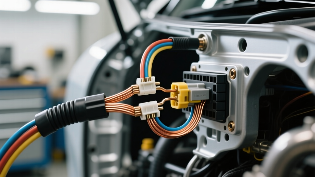
The Critical Role of 24 AWG in Modern Automotive Electrical Systems
When diagnosing and repairing modern vehicle networks, technicians often focus on high-current power circuits. However, the nervous system of a modern vehicle relies heavily on micro-circuitry and data lines where 24 gauge wire is the undisputed standard. Measuring just 0.0201 inches (0.51 mm) in diameter, 24 AWG is strictly reserved for low-current, high-sensitivity applications. These include Controller Area Network (CAN) bus communication lines, Local Interconnect Network (LIN) bus, 5-volt reference (5V REF) supplies, and analog signal returns for sensitive sensors like Mass Air Flow (MAF) and Oxygen (O2) sensors.
Because these circuits operate on millivolt thresholds and high-impedance signals, a poor repair on a 24 AWG wire can introduce resistance, electromagnetic interference (EMI), or voltage drop that will immediately trigger diagnostic trouble codes (DTCs) such as U0100 (Lost Communication) or P0131 (O2 Sensor Circuit Low Voltage). This guide provides a master-level, step-by-step approach to installing, splicing, and terminating 24 gauge wire in automotive environments.
Technical Specifications: 24 Gauge Automotive Wire
Automotive 24 AWG wire is typically manufactured to SAE J1128 standards, utilizing TXL (Thin-wall cross-linked) or GXL insulation to withstand under-hood temperatures up to 125°C (257°F) while maintaining a minimal outer diameter. Below are the core electrical specifications you must account for during installation:
| Specification | Measurement / Rating | Installation Impact |
|---|---|---|
| Conductor Diameter | 0.0201 in (0.511 mm) | Requires 24-30 AWG precision micro-strippers; standard strippers will sever strands. |
| Cross-Sectional Area | 0.205 mm² (404 Circular Mils) | Extremely low thermal mass; requires low-wattage, temperature-controlled soldering. |
| Resistance (at 20°C) | 25.67 Ω / 1,000 ft | High resistance over distance. A 10-ft round trip yields ~0.51 Ω, which can skew 5V REF signals. |
| Max Ampacity (Chassis) | ~3.5 Amps (Short runs) | Strictly for data/signals. Never use for 12V power feeds or ground returns for high-draw modules. |
| Insulation Type | TXL / GXL (Cross-linked) | Highly resistant to abrasion and chemicals, but requires higher heat to shrink tubing properly. |
Essential Tooling for Micro-Wire Installation
Attempting to repair 24 AWG wire with standard 10-22 AWG crimpers or wire strippers will result in severed copper strands and crushed terminals. To maintain the integrity of the circuit, your bench must include:
- Precision Wire Strippers: Tools specifically calibrated for 24-30 AWG (e.g., Titan 11240 or Knipex Micro-Strip). The cutting die must score the insulation without nicking the copper.
- Micro-Crimpers: Open-barrel crimpers designed for Molex Micro-Fit, Aptiv GT 150, or Deutsch DTM size 20 contacts.
- Temperature-Controlled Soldering Station: Set between 315°C and 350°C (600°F - 660°F) with a micro-pencil tip for tight harness access.
- Adhesive-Lined Heat Shrink: Dual-wall polyolefin with an inner layer of thermoplastic adhesive. This creates a waterproof seal and provides crucial strain relief for the fragile 24 AWG strands.
Step-by-Step Guide: Repairing a CAN Bus Twisted Pair
The CAN bus relies on differential signaling. CAN-High and CAN-Low transmit mirrored voltages. To reject common-mode electromagnetic noise, these two 24 AWG wires must be twisted together. According to the SAE J1939 standard, maintaining the twist rate is critical for network impedance and signal integrity.
Step 1: Access and Identify the Fault
Locate the damaged section of the CAN harness. Typical OEM CAN bus wire colors include White/Blue for CAN-H and White/Brown for CAN-L (though this varies by manufacturer; always consult the specific OEM wiring diagram). Carefully slit the harness loom longitudinally using a seam ripper to avoid slicing the delicate 24 AWG insulation.
Step 2: Staggered Stripping
Strip exactly 5mm (3/16 inch) of insulation from the 24 AWG conductors. Critical: Stagger your cuts. Cut the CAN-H wire 1 inch further back than the CAN-L wire. This prevents the bulky solder joints or crimp barrels from sitting parallel to one another, which would alter the characteristic impedance of the twisted pair and create a localized capacitor that degrades high-frequency data transmission.
Step 3: Solder and Seal
Slide a piece of adhesive-lined heat shrink over the main harness before splicing. For CAN bus repairs, a butt-splice solder sleeve (pre-filled with flux and solder rings) is highly recommended. Slide the sleeve over the stripped 24 AWG strands, align the copper, and apply heat evenly until the solder rings flow and the adhesive seals the edges. As noted by AutoShop 101's electrical training modules, solder sleeves provide the most consistent mechanical and electrical bond for micro-wires in high-vibration environments.
Step 4: Re-Twisting the Pair
Once the joints are cooled and sealed, you must re-twist the wires. Maintain the factory twist rate, which is typically one full twist every 0.5 to 1.0 inches. If the wires are left straight, the differential receiver in the ECU will not be able to cancel out EMI from adjacent high-current cables (like fuel injector or ignition coil feeds), resulting in intermittent U-code communication faults.
Step-by-Step Guide: Splicing a 5V Reference or O2 Sensor Signal
Analog sensors like the Throttle Position Sensor (TPS) or Manifold Absolute Pressure (MAP) sensor rely on a pristine 5V REF line and a clean signal return. These circuits draw less than 50mA, but the ECU measures the voltage drop across a potentiometer with millivolt precision. Adding even 0.2 ohms of resistance via a poor crimp on a 24 AWG wire can drop the 5V reference to 4.8V, causing the ECU to miscalculate engine load.
Step 1: The 'Western Union' Splice
Do not use butt connectors for analog signal wires. Instead, strip 10mm of the 24 AWG wire. Cross the bare strands in an 'X' shape and twist them tightly together using a Western Union (Lineman's) splice. This provides immense mechanical strength before the solder is even applied.
Step 2: Capillary Soldering
Apply a tiny amount of rosin-core solder to the joint. Because 24 AWG wire has very low thermal mass, it will heat up and accept solder almost instantly. Do not overheat the joint, as the heat will travel down the copper strands and melt the TXL insulation further down the wire, exposing bare copper to potential short circuits.
Step 3: Strain Relief Application
Cover the splice with 3/16-inch dual-wall adhesive heat shrink. The adhesive must melt and flow into the stranded wire gaps to prevent moisture intrusion. Moisture wicking through stranded 24 AWG wire (capillary action) is a leading cause of galvanic corrosion inside ECU connector cavities.
Common Failure Modes and Troubleshooting 24 AWG Circuits
When diagnosing issues post-repair, or when evaluating a factory harness for 24 AWG degradation, use this decision tree to isolate the root cause:
- Symptom: Intermittent U0001 / U0100 Codes (High Speed CAN Fault)
- Cause: Untwisted 24 AWG CAN wires routing too close to the alternator or ignition coils.
- Fix: Re-twist the pair to 1 twist per inch and reroute the harness at least 4 inches away from high-voltage/high-current sources.
- Symptom: P0125 or P0131 (O2 Sensor Slow/Low Voltage)
- Cause: Micro-fractures in the 24 AWG signal wire inside the insulation jacket, often caused by using the wrong wire strippers and nicking the copper strands during a previous repair.
- Fix: Perform a voltage drop test on the signal circuit under load. If voltage drop exceeds 50mV, cut out the damaged 24 AWG section and install a new pigtail using the solder-seal method.
- Symptom: MAP/TPS Sensor Out of Range (Code P0108 / P0222)
- Cause: High resistance on the 24 AWG 5V REF or Sensor Ground circuit due to terminal fretting corrosion at the ECU connector.
- Fix: Inspect the micro-terminals in the ECU cavity. Clean with electronic contact cleaner and apply a light coat of dielectric grease to the 24 AWG terminal seals to prevent future oxidation.
Final Verification and Harness Dressing
After completing any 24 AWG repair, the physical dressing of the harness is just as important as the electrical connection. Never pull a 24 AWG wire taut; always leave a slight service loop (slack) before it enters a rigid connector cavity or a grommet. Secure the harness using high-temperature Tesa tape or split-loom tubing, ensuring that the fragile micro-wires are routed in the center of the bundle, protected by the heavier 12 or 14 AWG power and ground wires on the outside. By respecting the physical and electrical limitations of 24 gauge wire, you ensure long-term reliability of the vehicle's most sensitive data and sensor networks.