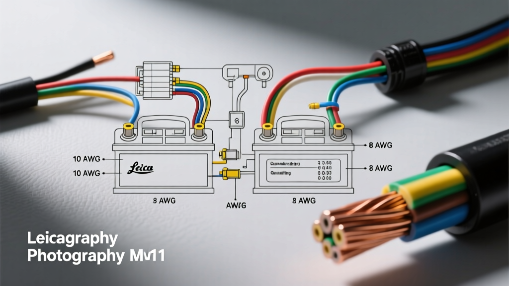
Introduction to High-Current Automotive Wiring Diagrams
When upgrading a heavy-duty truck, overland rig, or marine vessel with a dual battery system, reading the wiring diagram is only the first step. The true challenge lies in executing the build safely and efficiently. At the heart of every successful high-current electrical modification is a deep understanding of wire gauge current ratings. Unlike household alternating current (AC) wiring, automotive direct current (DC) systems operate at low voltages (12V to 24V nominal), meaning they require exponentially higher amperage to deliver the same wattage. This makes selecting the correct American Wire Gauge (AWG) not just a matter of preventing blown fuses, but of ensuring the entire system functions without catastrophic voltage drop or thermal failure. In this complete wiring diagram walkthrough, we will dissect a heavy-duty dual battery setup, analyzing the specific wire gauge current ratings required for each leg of the circuit.
Decoding Wire Gauge Current Ratings: The SAE J1128 Standard
Before tracing the diagram, we must establish the governing standard. In North America, automotive wire sizing is dictated by the SAE J1128 Standard. This specification outlines the construction, insulation materials, and most importantly, the wire gauge current ratings for low-tension automotive cables. The standard differentiates between insulation types like TXL (thin-wall, 125°C), GXL (general, 125°C), and SXL (special, 125°C cross-linked). Cross-linked polyethylene (XLPE) insulation allows the wire to withstand the extreme under-hood temperatures of a diesel engine bay, which directly impacts its ampacity. According to Blue Sea Systems' circuit engineering guidelines, bundling wires or routing them through high-heat zones requires derating the ampacity. Below is the baseline SAE J1128 ampacity chart for single, unbundled SXL wires in an engine compartment environment.
| AWG Size | Stranding Count | Resistance (Ohms/1000ft) | Max Ampacity (Engine Bay 125°C) | Typical Automotive Application |
|---|---|---|---|---|
| 4/0 AWG | 4204 | 0.0608 | 300A - 350A | Starter Motor, 3000W+ Inverter Main Feed |
| 2/0 AWG | 2632 | 0.0967 | 250A - 280A | High-Output Alternator Main Charge Line |
| 1/0 AWG | 2093 | 0.122 | 200A - 225A | Battery Isolator to Starter Battery |
| 2 AWG | 1330 | 0.194 | 150A - 175A | Isolator to Auxiliary Battery, Winch Control |
| 4 AWG | 836 | 0.308 | 100A - 120A | DC-DC Chargers, 1000W Inverter Feed |
| 8 AWG | 336 | 0.778 | 50A - 60A | Anderson Powerpole Plugs, Air Compressors |
| 12 AWG | 84 | 1.98 | 20A - 25A | Lighting Relays, Auxiliary Fuse Blocks |
| 18 AWG | 16 | 7.95 | 5A - 7A | VSR Trigger Signals, ECU Sense Wires |
Diagram Walkthrough Step 1: Alternator to Smart Isolator
Our walkthrough begins at the high-output alternator. In a modern heavy-duty truck (such as a 2020+ Ford Super Duty with a dual-alternator setup), the primary alternator may output 250 amps. Tracing the wiring diagram, the main positive output stud connects directly to the input terminal of a smart battery isolator or Voltage Sensitive Relay (VSR). Because this leg carries the full potential output of the alternator, referencing our wire gauge current ratings chart dictates the use of 2/0 AWG SXL wire. Using 1/0 AWG here would result in excessive resistance. At 250 amps, a 10-foot run of 1/0 AWG wire yields a voltage drop of approximately 0.61V. While that sounds negligible, in a 14.4V charging system, dropping below 13.8V at the VSR input can cause the smart relay to prematurely disengage, thinking the alternator is off. We terminate this 2/0 AWG red SXL cable with a heavy-duty M10 closed-end ring terminal, crimped with a 1-ton hydraulic press and sealed with dual-wall heat shrink containing a polyamide adhesive liner to prevent under-hood moisture ingress.
Diagram Walkthrough Step 2: Isolator to Auxiliary Battery
Moving past the VSR, the diagram splits. The VSR requires both heavy current paths and low-current signal wires. The main output to the auxiliary battery in the rear cargo area requires a long cable run—often 25 to 30 feet in a crew-cab truck. Here, wire gauge current ratings must be adjusted for distance. Even though the continuous draw to the rear battery might only be 80 amps during bulk charging, the 30-foot round-trip distance (60 feet total wire) demands upsizing to 2 AWG to maintain a voltage drop below 2% (0.28V). The diagram also shows an 18 AWG blue trigger wire routed from the ignition switch to the VSR's 'Start Sense' pin. This pin requires less than 100 milliamps to engage the internal solenoid. Using 18 AWG TXL wire here is perfect, protected by an inline 5A ATO fuse within 6 inches of the ignition tap.
Diagram Walkthrough Step 3: High-Draw Auxiliary Accessories
The auxiliary battery powers a 2000W pure sine wave inverter and a 12,000 lb winch via a remote Anderson SB175 connector. The wiring diagram specifies a 4/0 AWG main feed for the inverter. Why 4/0 AWG when the continuous draw of a 2000W inverter at 12V is roughly 166 amps? The answer lies in surge current ratings. Inverters experience massive inrush currents when starting inductive loads like microwaves or air compressors, momentarily spiking to 400 amps. If we relied strictly on continuous wire gauge current ratings and installed 2 AWG wire, the instantaneous voltage drop during surge would trigger the inverter's low-voltage cutoff, shutting down the appliance. The 4/0 AWG cable is protected by a 250A Class-T fuse. Class-T fuses are mandatory here over standard ANL fuses because of their high interrupting capacity (20,000 amps at 125VDC), preventing a catastrophic arc flash in the event of a dead short.
Voltage Drop Calculations and Real-World Failure Modes
When builders ignore wire gauge current ratings or attempt to substitute cheap Copper Clad Aluminum (CCA) wire for pure Oxygen-Free Copper (OFC), specific failure modes emerge. A common symptom in dual-battery diagrams is the auxiliary battery failing to reach full state-of-charge. A multimeter test at the alternator shows 14.2V, but the aux battery reads 13.1V. This 1.1V drop is almost always caused by undersized gauge wire or poor crimp connections adding parasitic resistance. Another severe failure mode is the melting of wire insulation near the firewall pass-through. This occurs when wire gauge current ratings are calculated for free-air routing, but the wire is bundled tightly with other harnesses inside a conduit, trapping heat and effectively halving the wire's ampacity. Always derate your wire gauge current ratings by 20% to 30% when routing through enclosed looms or firewall grommets.
Conclusion: Executing the Diagram with Precision
Mastering a complex automotive wiring diagram requires more than just connecting point A to point B. It requires a strict adherence to established wire gauge current ratings, an understanding of SAE J1128 material properties, and the foresight to calculate voltage drop across long chassis runs. By selecting the correct SXL wire, utilizing proper hydraulic crimps, and protecting the circuit with DC-rated Class-T or Mega fuses, you ensure that your heavy-duty electrical system is as reliable as the mechanical drivetrain it supports. Always consult manufacturer documentation and verified ampacity charts before cutting your first length of cable.