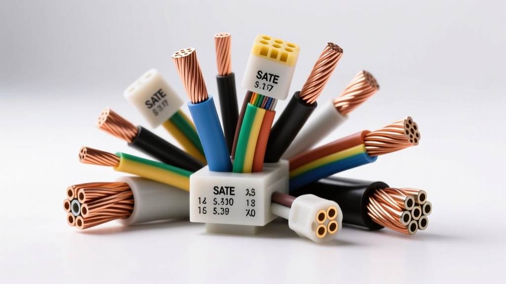
The Illusion of AWG: Why Wire Gauge Thickness Varies
When automotive technicians and engineers discuss wire gauge thickness, they frequently conflate the American Wire Gauge (AWG) number with the physical outer diameter of the cable. This is a fundamental misunderstanding of electrical standards. AWG strictly defines the cross-sectional conductive area of the copper, not the physical thickness of the conductor bundle, and certainly not the overall diameter including insulation. In high-current 12V systems and high-voltage EV architectures, relying solely on the AWG stamp can lead to catastrophic routing failures, improper crimping, and severe thermal derating issues.
According to SAE J1128 standards, a 1/0 AWG wire must have a minimum circular mil area of 105,600. However, the physical wire gauge thickness you measure with a micrometer will vary wildly depending on the stranding architecture, the packing factor, and the dielectric material used for the jacket. Understanding these variables is critical for designing robust power distribution networks in modern vehicles.
Cross-Sectional Area vs. Physical Diameter: The Stranding Factor
The physical thickness of the copper conductor itself is dictated by the stranding configuration. Automotive wiring generally falls into two categories: coarse-strand (standard primary wire) and fine-strand (welding or EV cabling). Fine-strand wire utilizes thousands of microscopic copper filaments. Because cylinders cannot pack perfectly without gaps, fine-strand wire has a lower "packing factor" (typically around 75-80% copper, with the rest being interstitial air). This means a fine-strand 1/0 AWG cable will have a physically thicker copper bundle than a coarse-strand 1/0 AWG cable, despite having the exact same cross-sectional conductive area and DC resistance.
| AWG Size | Strand Architecture | Strand Count | Conductor Dia (in) | Insulation Thickness (in) | Overall O.D. (in) | DC Resistance (Ω/1k ft) |
|---|---|---|---|---|---|---|
| 1/0 AWG | SAE J1128 (Coarse) | 1,064 (30 AWG) | 0.368 | 0.030 | 0.428 | 0.0983 |
| 1/0 AWG | SAE J1351 (Fine) | 4,536 (36 AWG) | 0.392 | 0.035 | 0.462 | 0.0983 |
| 2 AWG | SAE J1128 (Coarse) | 665 (30 AWG) | 0.292 | 0.030 | 0.352 | 0.1563 |
| 2 AWG | SAE J1351 (Fine) | 2,835 (36 AWG) | 0.311 | 0.035 | 0.381 | 0.1563 |
| 4 AWG | SAE J1128 (Coarse) | 420 (30 AWG) | 0.232 | 0.025 | 0.282 | 0.2485 |
As illustrated in the specification chart above, the overall physical thickness of a 1/0 AWG fine-strand cable is nearly 8% larger than its coarse-strand counterpart. This discrepancy becomes a massive headache when routing cables through tight firewall grommets or factory wire looms designed for thinner, coarse-strand OEM harnesses.
Insulation Materials and Thermal Derating in Bundled Harnesses
The dielectric jacket significantly impacts the final wire gauge thickness. Traditional PVC (Polyvinyl Chloride) insulation requires thicker walls to withstand engine bay temperatures (typically rated to 90°C or 105°C). In contrast, modern high-performance automotive wiring utilizes XLPE (Cross-Linked Polyethylene). XLPE offers superior thermal resistance (rated up to 125°C or 150°C) and exceptional chemical resistance against oil and fuel.
Because XLPE can handle higher thermal loads, manufacturers can extrude it in much thinner walls while maintaining the same dielectric breakdown voltage. Switching from PVC to XLPE can reduce the overall wire gauge thickness by 10-15%, saving critical weight and volume in dense power distribution modules (PDMs).
Calculating Bundled Derating Factors
When thick, high-current cables are bundled together in a conduit or loom, the physical thickness of the insulation traps heat. The Southwire Engineering Handbook and SAE guidelines mandate thermal derating for bundled conductors. If you bundle four 1/0 AWG XLPE cables carrying 150A each, the ambient temperature inside the bundle can easily exceed the 125°C rating of the insulation, leading to dielectric melting and short circuits. For bundles containing 4 to 6 conductors, you must apply an 80% derating factor to the wire's free-air ampacity. For 7 to 9 conductors, the derating factor drops to 70%.
Real-World Application: Upgrading to a 250A High-Output Alternator
When upgrading a heavy-duty truck or off-road vehicle to a 250A high-output alternator, 1/0 AWG wire is the minimum requirement to prevent voltage drop. However, the physical wire gauge thickness of 1/0 AWG fine-strand welding cable introduces specific mechanical challenges.
Routing and Minimum Bend Radius
Thick cables possess significant memory and stiffness. The general rule for fine-strand automotive cable is that the minimum bend radius must not be less than 8 times the overall outer diameter. For a 1/0 AWG fine-strand cable with an O.D. of 0.462 inches, the minimum bend radius is roughly 3.7 inches. Forcing a tighter bend will cause the copper filaments on the outside of the radius to stretch and work-harden, eventually snapping and reducing the effective cross-sectional area, which increases resistance and heat.
Termination Physics: Hex vs. Indent Crimping
Because of the air gaps inherent in thick, fine-strand wire, standard indent crimpers are entirely inadequate. An indent crimper will merely push the outer strands into the air voids, leaving the center of the bundle uncompressed. This creates a high-resistance joint that will melt under a 250A load. You must use a closed-die hex crimp tool. A hex crimp applies uniform radial pressure, collapsing the interstitial air gaps and cold-welding the copper filaments into a solid, homogeneous mass. According to IPC/WHMA-A-620 standards, a proper hex crimp on heavy-gauge wire must exhibit zero flyaway strands and a perfectly formed bellmouth at the terminal entry.
Torque Specifications for High-Amp Lugs
Physical thickness also dictates the hardware used for termination. When securing a 1/0 AWG ring terminal to a battery post or alternator B+ stud, the surface area of the lug must mate perfectly with the busbar. For an M8 (5/16") stainless steel stud, the terminal nut must be torqued to exactly 12-15 Nm (9-11 lb-ft). Under-torquing allows micro-movements that cause fretting corrosion; over-torquing will yield the copper lug, reducing its thickness and clamping force over time.
EV High-Voltage Cabling: Shielding and Skin Effect
In Electric Vehicle (EV) architectures, wire gauge thickness takes on a new dimension due to electromagnetic interference (EMI) shielding. High-voltage traction cables (typically Orange jacketed, ranging from 35mm² to 95mm², roughly equivalent to 2 AWG to 1/0 AWG) carry up to 800V DC and high-frequency AC from the inverter to the traction motors.
To prevent EMI from disrupting low-voltage CAN bus networks, these cables feature a braided copper or aluminum shield beneath the outer silicone or XLPE jacket. This shielding layer adds substantial physical thickness and rigidity to the cable. Furthermore, during high-frequency AC operation (such as PWM signals from the inverter), the "skin effect" causes current to travel primarily on the outermost filaments of the conductor. To combat this, EV cables often use specialized Roebel transposed conductors or ultra-fine stranding to maximize the effective surface area, further altering the physical thickness-to-conductivity ratio compared to standard 12V DC wiring.
Troubleshooting Crimp Failures Related to Thickness Mismatches
When working with heavy wire gauge thicknesses, improper tooling or misidentified wire types will result in predictable failure modes. Use this diagnostic matrix to identify issues:
- Barrel Cracking: Caused by using a die that is too small for the physical thickness of the terminal, or attempting to crimp a nickel-plated terminal which lacks the ductility of pure copper or tin.
- Flyaway Strands: Occurs when the wire gauge thickness was underestimated, and the conductor was not fully inserted into the terminal barrel before crimping, or when an indent crimper was used on fine-strand wire.
- Insulation Pinch: Happens when the overall O.D. of the wire (including thick XLPE or silicone jackets) is too large for the terminal's insulation support grip, causing the crimp to cut into the dielectric and create a short-circuit pathway.