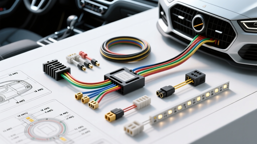
The Core Question: What Gauge Wire for LED Light Strips?
When integrating aftermarket illumination into a vehicle, the most common question enthusiasts and technicians ask is: what gauge wire for LED light strips is required for a safe, reliable 12-volt automotive system? The answer is never a single number. It depends entirely on the total amp draw of the LED chips, the length of the wire run from the power source, and the ambient temperature of the installation zone.
Using undersized wire in a 12V DC automotive environment leads to severe voltage drop, resulting in dimly lit strips, color shifting in RGBW setups, and in extreme cases, melted insulation and electrical fires. This step-by-step troubleshooting and reference guide will walk you through calculating your load, selecting the correct American Wire Gauge (AWG), and diagnosing common LED wiring failures using professional automotive electrical standards.
Phase 1: Calculate the True Amp Draw
Before selecting a wire gauge, you must determine the maximum current (amperage) the circuit will pull. LED light strips are categorized by their SMD (Surface Mounted Device) chip size and density. Always calculate based on the maximum white/brightness setting for RGBW strips, as this activates multiple diodes simultaneously.
| LED Chip Type | Density (LEDs/m) | Wattage (12V) | Max Amp Draw | Recommended Fuse |
|---|---|---|---|---|
| 3528 SMD (Standard) | 60 | 24W | 2.0A | 3A ATC |
| 5050 SMD (High Output) | 60 | 48W | 4.0A | 5A ATC |
| 2835 SMD (High Efficiency) | 120 | 72W | 6.0A | 7.5A ATC |
| COB (Continuous On Board) | 320+ | 96W | 8.0A | 10A ATC |
Phase 2: Factor in Voltage Drop and Wire Length
Unlike residential 120V AC wiring, 12V DC automotive systems are highly susceptible to voltage drop. According to SAE J1128 standards for low-tension primary cable, a 3% voltage drop is the maximum acceptable threshold for sensitive electronics. For a 12V system, a 3% drop equates to 0.36V. If your LED strip receives less than 11.5V, you will experience noticeable dimming and PWM controller errors.
Furthermore, vehicle charging systems operate at roughly 13.8V to 14.4V when the alternator is running. Wire sizing must account for the total round-trip distance (positive wire from battery to load, plus negative wire from load to chassis ground). If your strip is 8 feet from the battery, your total wire run for voltage drop calculations is 16 feet.
Phase 3: Wire Gauge Selection Chart
Use the following reference chart to determine the minimum AWG size based on your calculated amp draw and total round-trip wire length. This chart assumes standard copper stranded wire (GXL or TXL cross-linked polyethylene insulation, rated for 125°C to 150°C under-hood environments).
| Max Amps | 0-5 ft Run | 5-10 ft Run | 10-15 ft Run | 15-20 ft Run |
|---|---|---|---|---|
| 2.0A (3528 Strip) | 22 AWG | 20 AWG | 18 AWG | 18 AWG |
| 4.0A (5050 Strip) | 18 AWG | 16 AWG | 14 AWG | 12 AWG |
| 6.0A (2835 Strip) | 16 AWG | 14 AWG | 12 AWG | 10 AWG |
| 8.0A+ (COB Strip) | 14 AWG | 12 AWG | 10 AWG | 8 AWG |
Note: For runs exceeding 20 feet, or for high-density RGBW strips pulling over 10 amps, you must inject power at both the anode and cathode ends of the strip to prevent the copper traces on the LED PCB from burning out.
Phase 4: Step-by-Step Troubleshooting Flow
Even with the correct wire gauge, poor termination or incorrect circuit tapping can cause system failures. Use this diagnostic decision tree to troubleshoot common LED light strip issues in automotive applications.
Symptom A: Strip is Dim at the Far End (Voltage Drop)
- Diagnostic Step: Set a digital multimeter to DC Volts. Measure voltage at the battery terminals, then measure directly at the LED strip's positive and negative solder pads while the strip is illuminated at 100% brightness.
- Failure Mode: A voltage difference greater than 0.5V indicates excessive resistance. This is usually caused by using 18 AWG wire for a 6-amp COB strip over a long run, or relying on the thin copper traces of the strip itself to carry current the entire 16-foot length.
- Corrective Action: Upsize the primary feed wire (e.g., from 16 AWG to 12 AWG). If the strip is already installed and wires cannot be replaced, run a secondary 16 AWG power and ground injection wire to the far end of the strip, splicing it directly to the main feed.
Symptom B: Flickering in Sync with Engine RPM
- Diagnostic Step: Connect an oscilloscope or a multimeter with Min/Max recording to the 12V trigger wire. Watch for AC ripple or voltage spikes when the alternator is under load.
- Failure Mode: The LED strip is wired directly to a CAN-bus controlled interior lighting circuit, a PWM (Pulse Width Modulation) dimmer switch, or a shared ground with high-draw components like fuel pumps. Modern vehicles use PWM to dim interior lights, which causes aftermarket LEDs to strobe.
- Corrective Action: Isolate the LED circuit using a standard Bosch-style 4-pin automotive relay. Use the vehicle's PWM interior light wire only as a low-amp trigger signal, not as a power source.
Symptom C: Wire Insulation is Warm or Melting
- Diagnostic Step: Use an infrared thermometer to check the temperature of the wire insulation and the inline fuse holder. Check the ground connection for corrosion.
- Failure Mode: A poor chassis ground creates high resistance, forcing the circuit to pull excess current to compensate, or the wire gauge is severely undersized for the load (e.g., running an 8A load through 20 AWG speaker wire). Another cause is a short circuit partially grounding against the chassis, bypassing the strip.
- Corrective Action: Disconnect power immediately. Scrape away paint and clear coat at the ground location, use a star washer to bite into bare metal, and apply dielectric grease. Verify the wire matches the TechFlex Ampacity Chart recommendations for the specific load.
Phase 5: Automotive Termination and Relay Integration
Answering 'what gauge wire for LED light strips' is only half the battle; how you terminate that wire dictates the longevity of the installation. Never use twist-on wire connectors or electrical tape in a vehicle. Vibrations and thermal cycling will cause them to fail.
The Bosch Relay Wiring Standard
For any LED strip drawing more than 5 amps, or for strips triggered by a low-current switch, wire a standard ISO mini relay as follows:
- Pin 85: Chassis Ground (18 AWG Black wire, ring terminal).
- Pin 86: 12V Trigger Source (18 AWG Blue wire from switch or interior lighting module).
- Pin 30: 12V Battery Constant Power (12 AWG or 14 AWG Red wire, fused within 18 inches of the battery positive terminal).
- Pin 87: Load Output to LED Strip Positive (Sized according to Table 2, Red wire).
Wire Types and Crimping Best Practices
Always use GXL (General Cross-Linked) or TXL (Thin-wall Cross-Linked) wire for under-hood or exterior LED installations (like grille lighting or rock lights). These wires feature cross-linked polyethylene insulation that resists heat, oil, and abrasion far better than standard PVC wire. For interior cabin lighting, standard SAE J1128 PVC primary wire is acceptable.
Terminate all connections using nylon-insulated, heat-shrink butt connectors or open-barrel crimps. After crimping with a proper ratcheting crimper, apply a heat gun to shrink the adhesive lining, creating a waterproof seal that prevents copper oxidation and subsequent voltage drop over time.