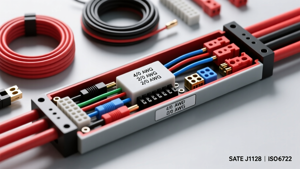
The Physics of Voltage Drop in High-Current DC Loops
When engineering high-amperage DC circuits—whether for 800V electric vehicle (EV) battery interconnects or 400A aftermarket alternator upgrades in off-road builds—selecting the correct electrical wire gauge transcends basic ampacity charts. It requires a rigorous analysis of voltage drop, thermal dissipation, and transient inrush currents. In a 12V or 24V DC system, voltage drop is the primary adversary. The fundamental formula for voltage drop is Vd = I × R, where I is current in amperes and R is the total resistance of the wire loop (positive and ground paths combined).
Copper has a resistivity of approximately 10.37 ohms-circular mils per foot at 20°C. As current increases, the I²R heating effect grows exponentially. For example, pushing 250A through a 15-foot run of 2 AWG wire (which has a resistance of 0.156 ohms per 1,000 feet) results in a loop resistance of roughly 0.00468 ohms. The voltage drop calculates to 1.17V. While this may seem negligible in a 400V EV system, in a 12V starter motor circuit, a 1.17V drop represents a nearly 10% loss of cranking voltage, directly reducing starter torque and potentially causing ECU brownouts during engine cranking.
SAE J1128 vs. SAE J1560: Insulation and Thermal Ratings
Automotive wire standards dictate not just the copper cross-section, but the thermal limits of the insulation. According to SAE J1128 specifications, standard primary automotive wire utilizes PVC insulation rated for continuous operation up to 125°C. However, in high-density engine bays or EV battery enclosures where ambient temperatures frequently exceed 85°C, PVC becomes brittle and loses dielectric strength.
For advanced high-amp applications, engineers must specify SAE J1560 compliant wire, which utilizes Cross-Linked Polyethylene (XLPE) or cross-linked PVC insulation rated for 150°C. XLPE insulation is significantly thinner than PVC, allowing for a tighter bend radius and better heat dissipation from the copper core. A 1/0 AWG XLPE cable will safely carry 20% more continuous current than a 1/0 AWG PVC cable in a confined, high-heat conduit due to its superior thermal conductivity and higher melting point.
Technical Specification Chart: 1 AWG to 4/0 AWG
The following reference table outlines the critical specifications for heavy-gauge automotive and EV wiring. Note that 'Chassis Wiring' ampacity assumes a single wire in free air at 30°C ambient, while 'Power Transmission' assumes bundled wires in a confined harness.
| AWG Size | Metric (mm²) | Circular Mils | Strand Count (Ultra-Flex) | Ohms / 1,000 ft (Cu) | Ampacity (Chassis) | Ampacity (Power Trans.) |
|---|---|---|---|---|---|---|
| 1 AWG | 42.40 | 83,690 | 1,064 (30 AWG strands) | 0.1239 | 211A | 119A |
| 1/0 AWG | 53.50 | 105,600 | 1,332 (30 AWG strands) | 0.0983 | 245A | 150A |
| 2/0 AWG | 67.40 | 133,100 | 1,666 (30 AWG strands) | 0.0779 | 283A | 192A |
| 3/0 AWG | 85.00 | 167,800 | 2,090 (30 AWG strands) | 0.0618 | 328A | 239A |
| 4/0 AWG | 107.20 | 211,600 | 2,646 (30 AWG strands) | 0.0490 | 380A | 302A |
Data references compiled from Southwire AWG Specifications and SAE standard conversion tables.
Real-World Application: 800V EV Battery Interconnects
In modern Electric Vehicles, the high-voltage (HV) battery pack relies on massive electrical wire gauge sizing to manage continuous discharge rates exceeding 600A during hard acceleration. These cables are universally jacketed in RAL 2003 Orange to signify lethal DC voltage. Furthermore, they are heavily shielded with a braided copper mesh to prevent Electromagnetic Interference (EMI) from disrupting the vehicle's CAN bus and low-voltage sensor networks.
Connector and Crimp Specifications
For 35mm² (approx. 2 AWG) to 50mm² (approx. 1/0 AWG) EV interconnects, the industry standard is the Amphenol SurLok Plus series. These connectors feature a radsocket contact design that minimizes contact resistance to less than 0.2 milliohms. When terminating 2 AWG shielded EV cable to a SurLok SLPIPB35BSO terminal:
- Stripping: Remove exactly 16mm of insulation. Do not nick the fine 30 AWG strands; a nicked strand creates a localized hot spot under high DC load.
- Crimping: Use a 6-ton hydraulic crimper with a hexagonal die matched precisely to the 35mm² ferrule. The crimp must achieve a minimum pull-out force of 350 lbs.
- Torque: When mating the connector to the battery busbar, the M8 mounting bolt must be torqued to exactly 22 Nm (16.2 lb-ft) using a calibrated dial torque wrench. Under-torquing leads to micro-arcing; over-torquing yields the busbar threading.
Real-World Application: 400A Alternator Upgrades (Off-Road & LS-Swaps)
When upgrading to a 400A alternator (such as a Mechman or Powermaster unit) for winching, heavy lighting, or mobile command centers, the factory 4 AWG or 2 AWG alternator output wire will instantly become a bottleneck, melting the insulation and triggering voltage drops. The correct electrical wire gauge for a 400A continuous output is 1/0 AWG ultra-flexible welding wire or SAE J1560 XLPE battery cable.
Routing and Fusing Protocol
The 1/0 AWG positive cable must route directly from the alternator B+ stud to the main battery positive terminal. It must never pass through a standard distribution block, as the internal busbars of most aftermarket blocks are not rated for 400A continuous thermal load. Protection must be provided by a Class T fuse or a 400A Mega Fuse mounted within 7 inches of the battery positive post. The ground path is equally critical: upgrade the engine block to chassis ground strap to a minimum of 2 AWG, and ensure the battery negative to chassis ground is also 1/0 AWG to prevent the alternator from seeking a ground path through the engine oil pan bolts or accessory brackets.
Skin Effect and PWM Motor Controllers
An often-overlooked phenomenon in advanced EV wiring is the 'Skin Effect' caused by Pulse Width Modulation (PWM) motor controllers. Controllers switch DC voltage at frequencies between 10 kHz and 20 kHz to simulate an AC sine wave. At these high frequencies, alternating current tends to travel primarily on the outer surface (the 'skin') of the conductor, effectively reducing the usable cross-sectional area of a thick, solid-core or coarse-strand wire. To combat this, high-end EV motor controllers require finely stranded Litz wire or ultra-flex SAE J1560 wire composed of thousands of micro-strands (e.g., 34 AWG individual strands bundled into a 1/0 AWG overall gauge). This maximizes the surface area available for high-frequency current propagation, reducing AC resistance and preventing localized harness overheating.
Failure Modes and Diagnostic Decision Tree
Even with the correct electrical wire gauge, improper installation leads to catastrophic failure. Use the following diagnostic tree when troubleshooting high-amp voltage drops:
- Symptom: Starter clicks slowly, or EV limits acceleration power.
- Test 1 (Millivolt Drop): Set a Fluke 87V multimeter to DC millivolts. Place probes across the entire length of the positive cable while under load (cranking or accelerating). Result > 100mV? Proceed to Test 2.
- Test 2 (Thermal Imaging): Use an infrared thermography camera (e.g., FLIR C5) to scan the harness under load. Hotspot localized at the terminal crimp? The crimp is voided or the wire was stripped too far, causing 'bellmouth' failure and strand oxidation.
- Test 3 (Galvanic Corrosion): Inspect the connection to aluminum busbars or intake manifolds. Copper and aluminum create a galvanic cell in the presence of moisture, resulting to high-resistance aluminum oxide buildup. Fix: Clean with a wire brush and apply a conductive antioxidant paste like PenetroxEJC or Noalox before re-torquing.
By adhering to strict SAE standards, calculating precise voltage drops, and utilizing proper hydraulic crimping techniques, you ensure that your high-amperage electrical wire gauge selections deliver reliable, loss-free power in the most demanding automotive environments.