Why Splicing Speaker Wire Matters in Car Audio Upgrades
When executing a comprehensive car audio upgrade, running new speaker wire from an aftermarket amplifier to the factory speaker locations is a mandatory step for achieving high-fidelity sound. However, navigating the vehicle's interior, door jambs, and tight harness routing often requires extending, adapting, or splicing speaker wire to reach its final destination. Understanding how to splice speaker wire correctly is not just about making an electrical connection; it is about preserving the amplifier's damping factor, preventing signal degradation, and ensuring the connection survives the harsh automotive environment.
A poor splice introduces unwanted resistance into the circuit. In mobile audio, increased DC resistance lowers the amplifier's damping factor, resulting in loose, muddy midbass and a loss of transient detail. Furthermore, automotive environments subject wiring to extreme thermal cycling, constant vibration, and high moisture levels, particularly when routing wires through A-pillars and into door hinge rubber boots. Standard household electrical tape and twist-on wire nuts will fail rapidly in these conditions. This guide details the professional methodologies for splicing speaker wire, focusing on gauge matching, environmental sealing, and long-term reliability.
Wire Gauge Selection and Damping Factor
Before making any splice, you must ensure the gauge of the extension wire matches or exceeds the gauge of the primary run. Using a thinner wire to bridge a gap creates a bottleneck that restricts current flow and alters the impedance curve seen by the amplifier. For most component and coaxial speakers (typically rated between 50W and 125W RMS), 16 AWG Oxygen-Free Copper (OFC) is the industry standard. For high-power midbass drivers or subwoofers, 14 AWG or 12 AWG is required.
According to the SAE J1128 Low Tension Cable Standard, automotive wiring must handle specific thermal and mechanical stressors. Always select OFC wire over Copper-Clad Aluminum (CCA). CCA wire has a higher resistance per foot and is highly susceptible to work hardening and snapping under the constant vibration of a vehicle door panel.
Speaker Wire Gauge Application Chart
| Wire Gauge (AWG) | Max Current (Amps) | Max Run Length (4-Ohm) | Ideal Application |
|---|---|---|---|
| 18 AWG OFC | ~9A | 12 Feet | Low-power rear fill (under 40W RMS) |
| 16 AWG OFC | ~13A | 20 Feet | Standard component/coaxial speakers (50-100W RMS) |
| 14 AWG OFC | ~17A | 30 Feet | High-power midbass, door woofers (100-200W RMS) |
| 12 AWG OFC | ~23A | 45 Feet | Subwoofers, high-current SPL builds |
The Danger of Galvanic Corrosion in Splices
A critical, often overlooked factor in car audio splicing is galvanic corrosion. If you splice CCA wire to OFC wire, or if you connect bare copper to factory tinned-copper wiring without proper sealing, the introduction of moisture (common in door panels) creates a galvanic cell. The dissimilar metals act as a battery, rapidly corroding the aluminum core of the CCA wire or oxidizing the copper. This results in a high-resistance, brittle connection that will eventually fail entirely. To prevent this, splices must be hermetically sealed using adhesive-lined dual-wall heat shrink or marine-grade crimp connectors, a best practice heavily emphasized by the Mobile Electronics Certification Program (MECP).
CTA Standard Speaker Wire Color Codes
When splicing into a factory harness or an aftermarket wiring block, maintaining proper polarity is critical for acoustic phase alignment. The Consumer Technology Association (CTA) established a standard color code for mobile electronics. Referencing the Crutchfield Speaker Wire Guide, adhering to these colors ensures that when you splice your new OFC runs into the factory plug, your speakers will move outward on the positive voltage swing.
| Speaker Channel | Positive (+) Wire Color | Negative (-) Wire Color |
|---|---|---|
| Front Left | White | White with Black Stripe |
| Front Right | Gray | Gray with Black Stripe |
| Rear Left | Green | Green with Black Stripe |
| Rear Right | Purple | Purple with Black Stripe |
Method 1: The Solder and Adhesive Heat Shrink Technique
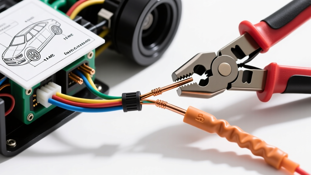
Soldering provides the lowest possible electrical resistance and creates a permanent metallurgical bond. When combined with adhesive-lined heat shrink, it forms a completely waterproof seal ideal for running through door jambs and under carpets.
- Preparation: Cut the adhesive-lined dual-wall heat shrink tubing to size (typically 1.5 inches for a standard splice) and slide it onto one side of the wire before stripping. If you forget this step, you will have to cut the splice and start over.
- Stripping: Use precision wire strippers to remove exactly 3/4 inch of insulation from both wire ends. Avoid nicking the copper strands, which creates weak points prone to fatigue failure.
- The Inline Twist: Cross the two exposed copper ends in an 'X' shape and twist them tightly together in opposing directions. This creates a strong mechanical bond before the solder even flows.
- Soldering: Apply a rosin-core solder (60/40 or lead-free equivalent) using a temperature-controlled iron. Heat the copper wire, not the solder directly. Allow the solder to wick completely into the twisted strands until it shines. A dull, gray joint indicates a 'cold solder' which will crack under vibration.
- Sealing: Slide the adhesive-lined heat shrink over the joint. Apply heat evenly with a heat gun. The outer wall will shrink, while the inner wall melts and extrudes out the ends, creating a waterproof, vibration-proof seal.
Method 2: Marine-Grade Crimp Connectors
If you are working in a tight space where a soldering iron is impractical or poses a fire risk to surrounding interior plastics, high-quality crimping is an acceptable alternative. Do not use cheap, nylon-insulated butt connectors; they will crack and allow moisture ingress.
- Select the Right Connector: Use marine-grade, adhesive-lined heat shrink butt splices. These feature a copper barrel (not brass or aluminum) and an inner meltable adhesive layer.
- Strip and Insert: Strip 5/16 inch of insulation. Insert the wires into the copper barrel, ensuring no bare copper is exposed outside the metal crimp zone, and no insulation is crimped inside the metal barrel.
- Ratcheting Crimp: Use a dedicated ratcheting wire crimper. The ratchet mechanism ensures that the exact amount of pressure is applied to cold-weld the copper strands to the barrel. Squeezing with pliers will deform the barrel and leave voids where corrosion can begin.
- Heat and Seal: Apply heat with a heat gun until the adhesive bubbles slightly from the ends, confirming a complete moisture seal.
Troubleshooting Bad Splices and Phase Issues
Even with meticulous work, issues can arise after reassembly. Use this diagnostic tree to identify splice-related failures in your upgrade project:
- Symptom: Muddy Bass / Lack of Impact
Cause: Out-of-phase wiring. One speaker is wired with reversed polarity, causing acoustic cancellation in the lower frequencies.
Fix: Use a 9V battery to briefly tap the speaker terminals. If the cone moves outward, the positive battery terminal is touching the positive wire. Verify your CTA color codes at the splice point. - Symptom: Intermittent Audio / Popping when Closing Door
Cause: Wire fatigue or a cold solder joint breaking inside the door jamb rubber boot.
Fix: Inspect the splice. If electrical tape was used, remove it. The wire has likely oxidized or snapped. Re-crimp using an adhesive-lined butt connector and ensure there is a 'service loop' (slack) in the wire so the door hinge does not pull the splice taut. - Symptom: High-Frequency Hiss or Alternator Whine in One Channel
Cause: A high-resistance splice acting as an antenna, or a ground loop introduced by splicing into a factory amplified system without a proper line output converter (LOC).
Fix: Check the resistance of the splice with a multimeter (should be near 0.1 ohms). If the splice is solid, verify that you are not splicing into a factory premium amplifier's data bus or biased speaker outputs.
Final Routing and Protection Best Practices
Once your splices are completed and sealed, the physical routing of the wire is just as critical as the electrical connection. When passing spliced wires through the vehicle's firewall or door hinges, always use a grommet. Never allow a splice to sit directly inside a rubber door boot where it will be subjected to repetitive crushing forces every time the door is opened and closed. Use Tesa tape (fabric harness tape) to bundle the spliced speaker wires together and secure them away from sharp metal edges, window tracks, and seat rails. By combining proper gauge selection, CTA color coding, and hermetically sealed connections, your car audio upgrade will deliver pristine sound and survive the lifetime of the vehicle.