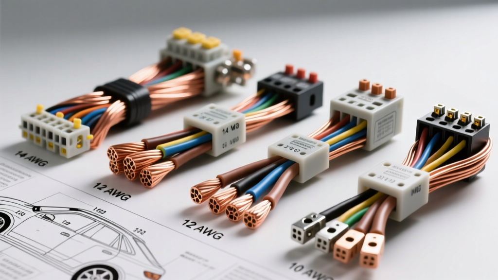
Introduction to Automotive Audio Current Draw
Car audio systems demand rigorous attention to electrical distribution. Unlike factory audio head units, which rarely exceed 10 to 15 amps of total system draw, aftermarket amplifiers can pull in excess of 150 amps continuously. Selecting the correct wire gauge for car stereo applications is not merely about preventing thermal events; it is about preserving amplifier headroom, preventing voltage sag, and eliminating ground-loop noise. This technical specification reference outlines the exact American Wire Gauge (AWG) requirements, voltage drop calculations, and termination standards necessary for high-fidelity mobile audio installations.
Conductor Material: OFC vs. CCA Standards
Before sizing your wire, you must identify the conductor material. The mobile electronics industry is flooded with Copper-Clad Aluminum (CCA) wire, which is significantly cheaper but electrically inferior to Oxygen-Free Copper (OFC). According to SAE International J1128 standards for low-tension primary automotive cable, pure copper provides optimal conductivity and thermal resistance.
- Oxygen-Free Copper (OFC): 100% copper conductivity. The baseline for all technical AWG sizing charts.
- Copper-Clad Aluminum (CCA): Possesses only ~61% of the conductivity of OFC. If you must use CCA, you are required to increase the wire diameter by 2 AWG sizes (e.g., use 4 AWG CCA to safely replicate the current capacity of 8 AWG OFC) to prevent voltage drop and thermal melting.
Power and Ground Wire Gauge Sizing Chart
The following chart dictates the minimum OFC wire gauge required based on the total continuous RMS wattage of your amplifiers. These calculations assume a 12.5V baseline (engine off/worst-case scenario) and account for amplifier efficiency (Class D at ~80% efficiency, Class AB at ~50% efficiency). A 20% safety margin is built into the max current draw column.
| Total RMS Wattage | Est. Max Current (Amps) | 0 - 10 ft Run (OFC) | 10 - 15 ft Run (OFC) | 15 - 20 ft Run (OFC) |
|---|---|---|---|---|
| 0 - 200W | 25A | 10 AWG | 8 AWG | 8 AWG |
| 200 - 400W | 45A | 8 AWG | 8 AWG | 4 AWG |
| 400 - 800W | 85A | 4 AWG | 4 AWG | 2 AWG |
| 800 - 1200W | 125A | 4 AWG | 2 AWG | 1/0 AWG |
| 1200 - 1800W | 180A | 2 AWG | 1/0 AWG | 1/0 AWG |
| 1800 - 2500W | 250A | 1/0 AWG | 1/0 AWG | 2/0 AWG |
| 2500W+ | 300A+ | 1/0 AWG (Dual Run) | 2/0 AWG | 3/0 AWG |
Calculating Voltage Drop in 12V Automotive Systems
Voltage drop occurs when electrical resistance in the wire consumes voltage before it reaches the amplifier. In a 12V nominal automotive system (operating between 12.6V and 14.4V), a voltage drop exceeding 0.3V (approx. 2.5%) will cause amplifiers to clip prematurely, trigger undervoltage protection circuits, and severely degrade audio output. As detailed in the Crutchfield Car Audio Power Wiring Guide, the formula for calculating voltage drop in a DC circuit is:
VD = (2 × L × I × R) / 1000
- VD: Voltage Drop
- L: Length of the wire run in feet (one way)
- I: Current draw in Amps
- R: Resistance of the wire per 1000 feet (e.g., 8 AWG OFC is ~0.6282 ohms/kft)
Example: An 800W Class D amplifier drawing 85A over a 15-foot run of 8 AWG OFC wire: VD = (2 × 15 × 85 × 0.6282) / 1000 = 1.60 Volts. This is a catastrophic 12% drop. Upgrading to 4 AWG (0.2485 ohms/kft) reduces the drop to 0.63 Volts, which is acceptable, though 2 AWG (0.1563 ohms/kft) yielding 0.39 Volts is the ideal technical specification.
Standard Head Unit Wiring and Signal Wire Gauges
When integrating the head unit to the vehicle harness or an amplifier integration module (like a PAC AudioPRO or Metra AXXESS interface), adherence to the EIA/TIA standard color codes is mandatory for troubleshooting. Standard aftermarket 16-pin ISO harnesses utilize specific gauges based on current load:
- Constant 12V (Yellow): 14 AWG (Carries memory and standby current)
- Switched 12V (Red): 16 AWG (Triggers head unit logic)
- Ground (Black): 14 AWG (Must be tied to a clean chassis ground, not a factory negative bus)
- Amp Turn-On (Blue/White): 18 AWG (Carries < 1A to trigger amplifier relays)
Speaker Wire Gauge and Impedance Matching
Speaker wire gauge is dictated by the impedance of the load and the length of the run. High-power component systems running at 2-ohms require thicker wire to prevent power loss and damping factor degradation. Refer to KICKER Amplifier Owner's Manuals for specific damping factor requirements.
| Speaker Impedance | 0 - 8 ft Run | 8 - 16 ft Run | 16 - 24 ft Run |
|---|---|---|---|
| 4-Ohm | 18 AWG | 16 AWG | 14 AWG |
| 2-Ohm | 16 AWG | 14 AWG | 12 AWG |
Standard Speaker Color Codes:
Left Front: White (+) / White w/ Black Stripe (-)
Right Front: Gray (+) / Gray w/ Black Stripe (-)
Left Rear: Green (+) / Green w/ Black Stripe (-)
Right Rear: Purple (+) / Purple w/ Black Stripe (-)
Termination, Fusing, and Hardware Specifications
Proper wire gauge selection is useless without correct termination. Bare wire stuffed under a battery terminal is a severe fire hazard and a primary cause of voltage drop.
- Terminals: Use closed-end, tin-plated copper ring terminals. For 4 AWG wire, use a 3/8" stud ring terminal. Crimp using a hex-indent hydraulic or heavy-duty ratchet crimper to achieve a gas-tight, cold-weld connection.
- Heat Shrink: Always seal terminations with dual-wall, adhesive-lined polyolefin heat shrink (3:1 shrink ratio). The inner adhesive melts to block moisture and prevent copper oxidation (verdigris).
- Fusing: ANL fuses are required for main power lines exceeding 80A. Maxi fuses are acceptable for 20A-60A runs. The main fuse must be located within 18 inches of the battery positive terminal to protect the vehicle from a dead short.
- Grounding Torque: When securing the main ground ring terminal to the vehicle chassis, strip the paint down to bare metal using a wire wheel, apply a dielectric grease to prevent oxidation, and torque the M8 or M10 bolt to 15-20 Nm (130-177 in-lbs).
Real-World Failure Modes and Troubleshooting
When wire gauge for car stereo systems is incorrectly specified, specific electrical symptoms manifest. Use this decision tree to diagnose gauge-related failures:
- Symptom: Amplifier shuts off during heavy bass transients.
Cause: Voltage sag due to undersized power wire or inadequate ground wire.
Fix: Measure AC voltage at the amp terminals during playback. If it exceeds 1.0V AC ripple, or DC drops below 11.5V, upgrade power and ground by 2 AWG sizes and add a 1.5 Farad capacitor or auxiliary AGM battery. - Symptom: High-pitched alternator whine that increases with engine RPM.
Cause: Ground loop caused by undersized ground wire, poor chassis contact, or routing RCA signal cables parallel to power wires.
Fix: Scrape chassis paint to bare metal, ensure ground wire is the exact same AWG as the power wire, and verify the resistance between the amplifier ground and the battery negative terminal is less than 0.05 ohms. - Symptom: Wire insulation feels hot to the touch or shows signs of melting near the amplifier block.
Cause: Using CCA wire instead of OFC, or severe over-fusing of an undersized cable.
Fix: Replace immediately with 100% OFC wire and recalibrate fusing to match the wire's ampacity, not just the amplifier's fuse rating.