Introduction: The Bottleneck in Factory Audio Upgrades
When upgrading from a factory head unit and low-power paper-cone speakers to an aftermarket DSP, external amplifiers, and high-excursion component sets, the factory wiring harness becomes the primary bottleneck. Most OEM manufacturers utilize 18 AWG to 22 AWG unshielded twisted pair (UTP) wiring for door speakers. While adequate for 15-watt RMS channels, pushing 100+ watts RMS through these thin conductors results in severe voltage drop, thermal degradation, and a compromised damping factor. For high-power car audio upgrades, transitioning to 12 gauge speaker wire is the industry standard for maintaining signal integrity and delivering clean current to your voice coils.
The Physics of Audio: Damping Factor and Voltage Drop
Speaker wire does not merely carry a low-voltage audio signal; it transports raw electrical current. The amplifier relies on a low-impedance path to maintain electromagnetic control over the speaker's voice coil, a metric known as the damping factor. When you use undersized wire, the resistance of the cable adds to the total load impedance. Excessive wire resistance reduces the amplifier's ability to 'brake' the speaker cone after a transient peak, resulting in muddy, uncontrolled mid-bass response.
Calculating Total Circuit Resistance
To understand why 12 gauge speaker wire is necessary for high-output builds, we must look at the math. The formula for continuous current draw is I = √(P/R). For a 100W RMS amplifier driving a 4-ohm load, the current draw is approximately 5 Amps (√(100/4) = 5A). True 12 AWG Oxygen-Free Copper (OFC) has a resistance of roughly 1.588 milliohms per foot. For a 15-foot run from the trunk to the front doors (30 feet total for positive and negative conductors), the total wire resistance is 0.047 ohms. While a voltage drop of 0.235V (5A x 0.047Ω) seems negligible, in low-impedance 2-ohm midbass applications where current doubles to 10A, the drop increases significantly. More importantly, that added 0.047 ohms directly degrades the damping factor, robbing your system of tight, punchy bass.
CTA-2015 Standards: OFC vs. CCA Wire
Not all 12 gauge speaker wire is created equal. The automotive electronics market is heavily saturated with Copper Clad Aluminum (CCA) wire, which coats an aluminum core with a microscopic layer of copper. Aluminum possesses only 61% of the conductivity of pure copper. Consequently, a 12 AWG CCA wire exhibits the DC resistance of a 14 or 15 AWG OFC wire. For automotive environments subject to extreme temperature fluctuations and physical vibration, OFC is mandatory. According to the Consumer Technology Association (CTA-2015 Mobile Electronics Standard), true AWG ratings must be calculated on pure copper. OFC wire utilizes 100% copper strands, typically featuring 65 to 168 individual strands per conductor to ensure flexibility and resistance to metal fatigue caused by door slams and chassis vibration.
Jacket Materials and Thermal Endurance
Inside a vehicle door, the internal metal skin can exceed 140°F (60°C) during summer months. Standard cheap PVC jackets can become brittle, crack, or off-gas plasticizers that degrade the copper over time. High-quality 12 AWG OFC wire utilizes Polyethylene (PE) or high-temp PVC jackets rated for at least 105°C (221°F), aligning with SAE J1128 thermal endurance requirements for automotive cabin wiring. Always verify the jacket material before installing wire inside enclosed door cavities.
Vehicle Routing Guide: Running 12 AWG Through Door Jambs
The most challenging aspect of a full vehicle rewire is passing thick 12 AWG wire (which typically measures 3.2mm to 3.8mm in outer diameter) through the factory rubber door boots. In vehicles like the Ford F-150 SuperCrew or Chevrolet Silverado Crew Cab, the run from the B-pillar to the rear doors can exceed 8 feet, making 12 AWG essential to keep voltage drop below 3%.
Step-by-Step Chassis Penetration
- Disconnect Power: Always disconnect the negative battery terminal to prevent shorting the amplifier outputs to the chassis ground, which can instantly destroy the amplifier's output stage.
- Expose the Boot: Unclip the factory rubber door jamb boot from both the A/B-pillar and the door hinge side. Use a plastic trim removal tool to avoid tearing the aging rubber.
- Deploy a Fish Tape: Use a flexible fiberglass fish tape or a stiffened wire coat hanger with a smooth, taped loop at the end. Never use sharp metal hooks that can pierce factory CAN-bus or airbag wiring.
- Lubricate the Jacket: Coat the 12 gauge speaker wire jacket with a generous layer of silicone dielectric grease to reduce friction against the factory harness.
- Feed the Wire: Feed the wire alongside the factory harness. Crucial Warning: Never wrap the new wire tightly around the factory harness. The heavier gauge can pull and snap the delicate 22 AWG factory data wires over time due to vibration.
- Re-seal the Grommets: Re-seat the rubber grommets firmly. Ensure the moisture seal is intact to prevent cabin water leaks and wind noise.
Termination Standards: Preventing the 'Green Death'
Bare copper oxidizes rapidly when exposed to the humidity and temperature swings inside a vehicle door cavity. This oxidation creates a high-resistance semiconductor layer (often called the 'green death') that acts as a diode, severely degrading high-frequency audio response. All 12 AWG speaker wire terminations must be sealed. If connecting to an aftermarket speaker's push terminals, use closed-end spade connectors crimped with a ratcheting crimper, followed by adhesive-lined marine-grade heat shrink. If soldering directly to the voice coil tabs or passive crossover network, use rosin-core silver-bearing solder and seal the joint with liquid electrical tape or conformal coating. For detailed installation best practices, refer to the Crutchfield Car Audio Installation Guides.
12 AWG OFC Speaker Wire Application Matrix
| Amplifier RMS Output | Nominal Impedance | Max Recommended Run Length (1-Way) | Expected Voltage Drop |
|---|---|---|---|
| 50W | 4 Ohms | 25 Feet | < 1.5% |
| 100W | 4 Ohms | 18 Feet | < 2.5% |
| 150W | 2 Ohms | 12 Feet | < 3.0% |
| 200W | 2 Ohms | 8 Feet | < 3.5% |
Common Failure Modes in Aftermarket Speaker Wiring
Symptom: Alternator Whine in the Speakers
Cause: Running 12 gauge speaker wire parallel to the vehicle's high-current charging wire or RCA signal cables, inducing electromagnetic interference (EMI).
Fix: Audio and power cables must cross at 90-degree angles. If they must run parallel along a rocker panel, maintain a minimum 6-inch separation between the power wire and the speaker/RCA cables.
Symptom: Intermittent Channel Dropout Over Bumps
Cause: Wire fatigue and internal strand breakage at the door hinge pivot point.
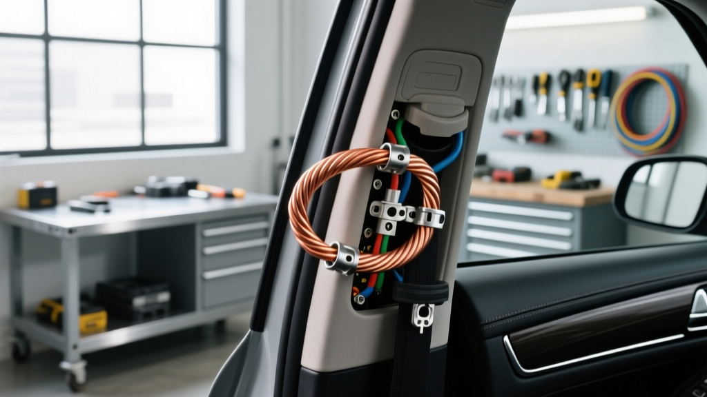
Fix: Create a 'service loop' (a small S-curve of extra wire) inside the door cavity and pillar. This loop absorbs the mechanical stress of the hinge articulation, preventing the copper strands from work-hardening and snapping.
Symptom: Amplifier Thermal Protection at High Volumes
Cause: Voice coil impedance dropping below the amp's stable threshold due to undersized wire acting as a resistor, generating heat, or stray 12 AWG strands shorting against the metal door skin.
Fix: Verify wire is true OFC 12 AWG, not CCA. Inspect all termination points and use heat shrink to ensure no stray copper strands are touching the grounded metal door chassis.