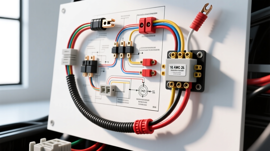
Introduction to 25-Amp Automotive Circuit Diagnostics
When diagnosing high-draw automotive accessories—such as in-tank fuel pumps, power seat motors, or high-amperage cooling fan relays—verifying the correct 25 amp wire gauge is only the first step in ensuring circuit reliability. A circuit designed to pull 25 amps continuously operates at the upper threshold of many standard automotive connectors and wire sizes. When these circuits degrade, the symptoms often mimic a failing component: fuel pumps whine or lose pressure under load, and power seats stall or trip thermal breakers. However, the root cause is frequently excessive resistance within the wiring harness or connector terminals.
As an automotive electrical diagnostician, relying on a visual inspection of the wire thickness is insufficient. Copper stranding degrades, insulation hardens, and terminal crimps loosen due to thermal cycling. This step-by-step troubleshooting flow will guide you through isolating voltage drop, verifying SAE J1128 wire specifications, and testing terminal integrity in high-draw 25-amp circuits.
Step 1: Verify the Baseline 25 Amp Wire Gauge Selection
Before testing for faults, you must confirm that the installed wire is actually rated for a 25-amp continuous load. In automotive chassis wiring, the SAE J1128 standard dictates current-carrying capacity based on ambient temperature and wire bundle size. While 12 AWG wire is sometimes used for short-run 20-amp circuits, a true continuous 25-amp load requires 10 AWG stranded copper to prevent thermal degradation and excessive voltage drop over distances greater than 6 feet.
AWG Specification Matrix for 25-Amp Loads
| Wire Gauge (AWG) | Ohms per 1,000 ft | Max Continuous Amps (Chassis) | Recommended Application for 25A Load |
|---|---|---|---|
| 10 AWG | 1.019 Ω | 30 Amps | Ideal for runs over 5 feet (Fuel Pumps, Power Seats) |
| 12 AWG | 1.619 Ω | 20-25 Amps | Acceptable only for short jumper runs (< 3 feet) |
| 8 AWG | 0.641 Ω | 40-50 Amps | Overkill for 25A, but required if bundling >4 wires |
Note: If you are troubleshooting an aftermarket fuel pump installation drawing 25 amps and find 12 AWG wire routed more than 8 feet from the relay to the tank, the wire gauge itself is the primary failure point. Upgrade to 10 AWG immediately.
Step 2: Execute the Voltage Drop Test Under Load
Voltage drop testing is the definitive method for diagnosing resistance in a 25 amp wire gauge circuit. You cannot perform this test with the circuit powered off; an ohmmeter will often read 0.1 ohms on a degraded wire, but under a 25-amp load, that same wire will choke the circuit. You must test the circuit while it is actively drawing current.
Testing the Positive Feed Circuit
- Set your Digital Multimeter (DMM): Configure your meter to DC Millivolts (mV). A standard Fluke 87V is ideal for capturing fluctuating readings under load.
- Connect the Probes: Place the red probe directly on the battery positive post (not the clamp, the actual lead post). Place the black probe on the load side of the circuit (e.g., the fuel pump positive pin at the tank harness connector).
- Activate the Circuit: Command the fuel pump on via a bidirectional scan tool, or jumper the fuel pump relay in the under-hood fuse block. Ensure the circuit is pulling its full ~25-amp load.
- Read the Drop: A healthy 10 AWG positive feed should exhibit a voltage drop of less than 0.200V (200mV). If your meter reads 0.500V or higher, you have excessive resistance in the positive cable, relay contacts, or inline fuse holders.
Testing the Ground Return Circuit
Ground side voltage drop is equally critical. Move your red DMM probe to the load side of the ground circuit (the black wire pin at the component) and your black DMM probe to the battery negative post. Under a 25-amp load, the ground side drop should not exceed 0.100V (100mV). High ground resistance forces the component to work harder, increasing amperage draw and accelerating component failure.
Step 3: Inspect Metri-Pack 280 Connector Terminals
If your voltage drop test isolates the resistance to a specific harness section, the next suspect is the connector. For 25-amp circuits, OEM manufacturers predominantly use the Delphi Metri-Pack 280 series connectors. The '280' refers to the 2.8mm blade width, which is engineered to handle up to 30 amps continuously when properly crimped.
Terminal Pin Drag and Crimp Depth Verification
A common failure mode in 25-amp circuits is terminal fretting and loss of pin retention force. When a fuel pump draws 25 amps, the Metri-Pack 280 terminal heats up. If the crimp was performed with improper tooling (e.g., using a generic crush crimper instead of a ratcheting die-specific tool), the copper strands will oxidize inside the crimp barrel. This creates a high-resistance hotspot that melts the plastic connector housing.
- The Pin Drag Test: Disconnect the harness and use a matching male test pin. Insert it into the female terminal. You should feel a distinct, firm 'click' and significant drag upon removal. If the test pin slides in and out with zero resistance, the terminal tangs are fatigued. The terminal must be extracted and replaced.
- Inspect the Bellmouth Crimp: Strip back the heat shrink on the wire side of the terminal. A proper crimp will show a slight flare (bellmouth) at the rear of the wire barrel. This prevents the sharp edge of the terminal from shearing the copper strands under engine vibration.
- OEM Wire Color Codes: When repairing, maintain OEM color coding to aid future diagnostics. For example, GM LS-platform fuel pump harnesses typically use 10 AWG Grey for the 12V+ feed and 10 AWG Black for the ground. Ford applications often use Pink/Black for the 12V+ feed and Black/Yellow for the ground.
Step 4: Thermal and Inductive Load Diagnostics
When a voltage drop test indicates a problem, but the wire length and gauge are correct, you must locate the exact point of resistance. Because a 25 amp wire gauge circuit generates measurable heat when resistance is present, thermal diagnostics are highly effective.
Using an Inductive Amperage Clamp
Clamp a DC-capable inductive ammeter around the 10 AWG positive feed wire. If the component (like a PWM-controlled fuel pump) is drawing 32 amps instead of the specified 25 amps, the component is likely binding, or the ground circuit is severely restricted, causing the motor to pull excess current to compensate for the voltage deficit. Conversely, if the draw is only 18 amps but the pump is commanded to 100%, the positive feed is choked by resistance, starving the motor of current.
Infrared Thermometer Scanning
With the circuit under load for 3 to 5 minutes, use an infrared thermometer or thermal imaging camera to scan the length of the harness. Focus heavily on inline fuse holders, aftermarket relay splices, and connector backs. A healthy 10 AWG wire carrying 25 amps should remain near ambient under-hood temperature. If a specific 2-inch section of the wire or a connector housing is 40°F hotter than the surrounding harness, you have found your localized resistance point. Cut out the degraded section, solder and heat-shrink the repair, or preferably, replace the entire pigtail using OEM-grade sealed connectors.
Common Failure Modes in High-Draw Accessories
Understanding where 25-amp circuits typically fail saves diagnostic time. Here are the most frequent real-world scenarios encountered in the shop:
1. Aftermarket Fuel Pump Relay Kits
Enthusiasts often install aftermarket relay kits to upgrade fuel delivery for forced induction. A frequent error is using 12 AWG wire for the main power feed from the battery to the relay, and then to the trunk. While the wire may be rated for 25 amps in free air, routing it through the interior cabin or near exhaust components derates its thermal capacity. Always use 10 AWG or 8 AWG for the main battery feed in these kits, reserving the 25 amp wire gauge calculations for the short, protected runs.
2. Power Seat Circuit Breakers Tripping
Power seats use auto-resetting thermal circuit breakers. If the seat tracks bind, the motors draw excess current. However, if the tracks are lubricated and the motors test fine on a bench, the issue is often voltage drop in the seat harness flex loop. The constant bending of the harness under the seat causes the copper strands inside the 10 AWG wire to fracture individually. The wire insulation looks perfect, but the internal cross-sectional area is reduced by 50%, turning the wire into a resistor. Perform a voltage drop test while actively moving the seat to catch this intermittent open.
3. Alternator Ripple Interference
High-draw 25-amp circuits are sensitive to dirty DC power. If the alternator diode trio is failing, AC ripple voltage will superimpose onto the DC feed. This causes severe overheating in the windings of DC motors (like fuel pumps and cooling fans), making them draw more than 25 amps and melting the harness. Always check AC ripple voltage at the battery (should be less than 50mV AC) before condemning a newly installed 25-amp wiring harness.
Summary
Troubleshooting a 25 amp wire gauge circuit requires moving beyond simple continuity checks. By verifying SAE J1128 gauge requirements, executing dynamic voltage drop tests under load, inspecting Metri-Pack 280 terminal integrity, and utilizing thermal diagnostics, you can accurately pinpoint the root cause of high-draw circuit failures. Proper diagnosis ensures that high-amperage automotive accessories receive the clean, unrestricted current they require for long-term reliability.