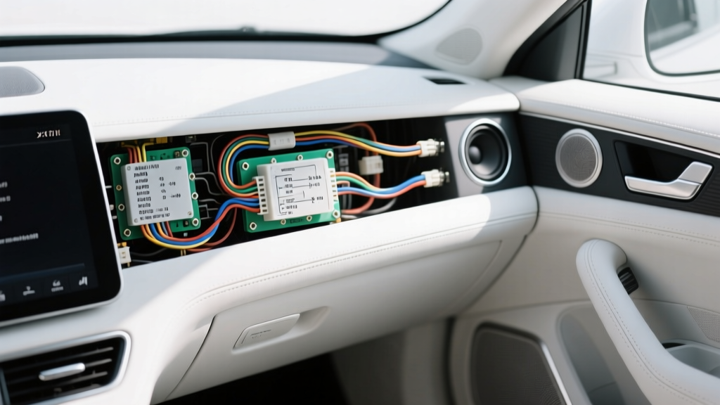
Introduction: The "What Gauge Speaker Wire Do I Need" Dilemma
When upgrading a vehicle's audio system, enthusiasts frequently ask, "what gauge speaker wire do i need?" Unlike power cables, where the primary concern is preventing catastrophic thermal failure or fire, speaker wire sizing in car audio is fundamentally about preserving signal integrity, maintaining the amplifier's damping factor, and preventing thermal compression. Using undersized wire won't necessarily burn your car down, but it will rob your midbass drivers of impact, muddy your low-frequency response, and introduce phase shifts across the audio spectrum.
This guide utilizes a step-by-step troubleshooting and diagnostic flow to help automotive electrical installers and DIY enthusiasts determine the exact American Wire Gauge (AWG) required for their specific application. We will cover impedance calculations, routing constraints through factory door boots, and how to troubleshoot existing audio systems suffering from improper wire sizing.
Phase 1: System Diagnostics & Load Calculation Flow
Before cutting any wire, you must establish the electrical demands of your specific speaker configuration. The required gauge is dictated by three variables: RMS Wattage, Speaker Impedance (Ohms), and Total Wire Run Length.
Step 1: Identify True RMS Output and Impedance
Ignore "Peak" or "Max" wattage ratings printed on speaker boxes; these are marketing metrics with no basis in electrical engineering. You must use the continuous Consumer Technology Association (CTA) certified RMS wattage. Furthermore, a speaker's nominal impedance (typically 4-ohms for standard coaxial and component sets, or 2-ohms for high-power midbass drivers) dictates current draw. According to Ohm's Law (I = P/V), a 2-ohm speaker pulling 300W RMS draws significantly more current than a 4-ohm speaker pulling the same wattage, necessitating a thicker wire to minimize resistance.
Step 2: Calculate the Damping Factor Impact
The damping factor is the amplifier's ability to control the mechanical movement of the speaker cone, specifically stopping it after a transient bass hit. High series resistance from thin, undersized speaker wire degrades the damping factor. If you are running high-excursion 6.5" midbass drivers in custom door pods, the wire resistance must be kept below 5% of the speaker's nominal voice coil resistance to maintain tight, accurate bass response.
Step 3: Measure the Automotive Wire Run
Measure the actual routing path, not the straight-line distance. In a standard 4-door sedan or truck, running wire from a trunk-mounted amplifier to the front doors involves routing under door sill plates, up through the A-pillar or B-pillar, and through the factory rubber door jamb boots. A front speaker run can easily exceed 12 to 15 feet per channel. Always calculate gauge requirements based on the one-way distance from the amplifier to the farthest speaker in the circuit.
Phase 2: Speaker Wire Gauge Specification Chart
Use the following diagnostic specification chart to select your baseline AWG. This chart assumes the use of pure Oxygen-Free Copper (OFC) stranded wire. If you are using Copper-Clad Aluminum (CCA), you must step up one full AWG size (e.g., use 12 AWG CCA to achieve 14 AWG OFC performance) due to aluminum's lower conductivity.
| AWG Size | Max RMS (4-Ohm) | Max RMS (2-Ohm) | Max Run Length (ft) | Typical Application |
|---|---|---|---|---|
| 18 AWG | 50W | 25W | 12 ft | Factory head unit to rear deck coaxials |
| 16 AWG | 100W | 50W | 15 ft | Standard 4-ohm door speakers (50-75W RMS) |
| 14 AWG | 150W | 75W | 20 ft | High-power component sets, tight door boot routing |
| 12 AWG | 300W | 150W | 25 ft | 2-ohm midbass drivers, subwoofer bridged runs |
| 10 AWG | 500W+ | 250W+ | 30 ft | High-SPL competition midbass, trunk subwoofers |
Phase 3: Troubleshooting Existing Audio Issues (Symptom-Cause-Fix)
If you are diagnosing an existing installation and asking "what gauge speaker wire do i need" because the current setup sounds poor, follow this diagnostic decision tree.
Symptom A: Muddy Bass and Loss of Transient Impact
- Diagnostic Step: Set a Digital Multimeter (DMM) to AC Voltage (mV range). Play a 50Hz sine wave test tone at 50% of the amplifier's rated RMS output. Measure the AC voltage directly at the amplifier's speaker terminals (V1), then measure at the speaker's basket terminals (V2).
- Analysis: Calculate the voltage drop (V1 - V2). If the drop exceeds 0.25V on a high-current midbass run, the wire resistance is too high, destroying the damping factor.
- The Fix: The existing wire is likely 16 AWG CCA or undersized 18 AWG. Rip out the old wire and upgrade to 12 AWG or 14 AWG high-strand-count OFC wire to restore amplifier control over the voice coil.
Symptom B: High-Frequency Roll-Off and Tweeter Starvation
- Diagnostic Step: Inspect the termination points at the crossover network or tweeter. Look for green/white oxidation (copper oxide) or gray powdery corrosion (aluminum oxide) under the heat shrink or crimp caps.
- Analysis: High frequencies are highly susceptible to connection resistance. If CCA wire was used and improperly terminated, the aluminum core oxidizes rapidly in the humid environment of a car door, creating a low-pass filter effect that kills treble clarity.
- The Fix: Cut back the oxidized wire by at least two inches. Strip fresh wire, and if using CCA, you must solder the connection using rosin-core solder and seal it with adhesive-lined polyolefin heat shrink to block moisture. For a permanent fix, replace the run with pure OFC wire.
Symptom C: Wire Pinching and Intermittent Audio Dropouts
- Diagnostic Step: Open the door and inspect the factory rubber door jamb boot. Pull back the rubber grommet and check for exposed copper or pinched insulation where the wire passes from the cabin into the door.
- Analysis: Installers often try to force thick, stiff 12 AWG power wire or low-strand-count speaker wire through tight factory boots. The repeated opening and closing of the door fatigues the copper strands, causing them to snap internally, leading to intermittent dropouts or complete failure.
- The Fix: Downsize to a highly flexible 14 AWG or 16 AWG wire with a high strand count (e.g., 4133 strands of 36 AWG copper). High-strand wire flexes without fatiguing. Apply dielectric grease to the rubber boot to reduce friction during door articulation.
Phase 4: Automotive Routing, Materials, and Termination
Selecting the right gauge is only half the battle; the material composition and termination methods dictate the longevity of the installation in a harsh automotive environment.
OFC vs. CCA: The Conductivity Reality
When sourcing wire, you will encounter Oxygen-Free Copper (OFC) and Copper-Clad Aluminum (CCA). CCA wire is cheaper and lighter but possesses only about 60% of the conductivity of pure copper. According to standard SAE J1128 primary cable guidelines adapted for mobile electronics, a 12 AWG CCA wire has the same current-carrying capacity as roughly a 15 AWG OFC wire. For high-fidelity car audio, always mandate pure OFC to ensure the AWG rating on the jacket matches the actual copper cross-section.
Debunking the Skin Effect Myth
Do not waste money on exotic, ultra-thick stranded "skin effect" wire for car audio. Skin effect—the tendency of alternating current to travel on the outer edge of a conductor—only becomes a significant factor at radio frequencies (MHz and GHz ranges). In the 20Hz to 20kHz audio spectrum, current flows uniformly through the entire cross-section of the copper wire. Standard, tightly bundled multi-strand OFC wire is electrically superior and physically more flexible for automotive routing.
Proper Termination Techniques
Avoid using "Scotchlok" T-taps or twist-on caps, especially when tapping into factory wiring for signal upgrades. These create loose mechanical connections that vibrate loose over time and invite moisture. For aftermarket speaker installations:
- Use crimp connectors with a proper ratcheting crimper tool to ensure a cold-weld mechanical bond.
- For high-RMS applications, solder the stranded wire to the speaker spade terminals using a temperature-controlled iron to avoid melting the delicate voice coil former.
- Always seal the termination with dual-wall, adhesive-lined heat shrink. When heated, the inner polyolefin layer melts and seals out the extreme humidity and condensation inherent to automotive door panels, preventing galvanic corrosion between the copper wire and the speaker's nickel-plated terminals.
Summary Diagnostic Checklist
To finalize your installation plan, verify these final points before pulling wire through the vehicle chassis:
- Head Unit Direct: 18 AWG OFC is sufficient for 4x50W max (approx. 15-20W RMS) head unit channels.
- Amplified Door Speakers: 16 AWG OFC for standard 50-75W RMS components; 14 AWG OFC for 100W+ RMS midbass drivers.
- Subwoofers: Never use standard speaker wire for subwoofers. Use 12 AWG to 8 AWG OFC power wire depending on the enclosure distance and total RMS load.
- Routing: Always use a wire fish tape and lubricant when pulling through factory door boots to prevent stretching the copper strands.
By following this diagnostic flow, you eliminate guesswork and ensure your car audio system receives the unimpeded electrical current required for reference-level sound quality. For more detailed wiring schematics and amplifier matching guides, consult Crutchfield's comprehensive car audio wiring resources and your amplifier manufacturer's CTA-2006 certified specification sheets.