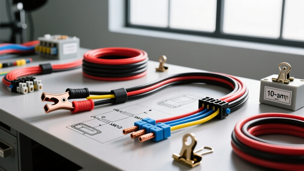
The 10 Amp Wire Gauge Dilemma: Why Thinner Is Not Better
When designing, upgrading, or repairing automotive electrical systems, selecting the correct 10 amp wire gauge is one of the most frequently misunderstood tasks in the garage. A 10-amp circuit is incredibly common in modern and classic vehicles, powering everything from LED auxiliary light bars and fuel pump controllers to horn relays, ECU switched-power feeds, and interior accessory lighting. However, the margin for error on a 10-amp circuit is deceptively narrow. Choose a wire that is too thin, and you risk catastrophic insulation meltdown, voltage starvation to sensitive electronics, or an under-hood electrical fire. Choose a wire that is excessively thick, and you will struggle with terminal crimping, connector insertion, and routing through tight firewall grommets.
At AutoFlowWire, we routinely diagnose electrical gremlins and burnt harnesses that trace back to fundamental misunderstandings of wire ampacity, temperature derating, and fuse coordination. This guide dissects the most dangerous mistakes enthusiasts and technicians make when sizing wire for 10-amp automotive loads, providing actionable, SAE-compliant safety warnings to keep your vehicle's electrical system reliable and fire-free.
SAE J1128 Standards: Selecting the Correct AWG for 10A Loads
The most common question we receive is: What is the exact 10 amp wire gauge? According to standard chassis wiring practices, 16 AWG wire is generally rated for up to 15 amps in open air. However, automotive environments are rarely 'open air.' Wires are bundled in harnesses, wrapped in split-loom, and routed through engine bays where ambient temperatures routinely exceed 100°C (212°F).
Under the SAE J1128 standard for Low Tension Primary Cable, wire insulation type dictates thermal resilience. Standard PVC-insulated wire (GPT) is rated for 105°C. In a high-heat engine bay, a 16 AWG GPT wire carrying a continuous 10-amp load will experience severe thermal degradation over time, leading to brittle insulation and eventual short circuits. For under-hood 10-amp applications, you must step up to 14 AWG wire, or at minimum, use Cross-Linked Polyethylene (XLPE) insulated wire such as GXL (125°C rating) or SXL (150°C rating).
Cross-Sectional Area and Resistance Specifications
- 16 AWG (GXL/TXL): 1.31 mm² cross-section, ~4.016 Ohms per 1,000 ft. Ideal for cabin 10A circuits (e.g., radio memory, dash illumination).
- 14 AWG (GXL/TXL): 2.08 mm² cross-section, ~2.525 Ohms per 1,000 ft. The mandatory standard for under-hood 10A circuits (e.g., horn relays, transmission solenoids).
Safety Warning: Never use 18 AWG wire for a continuous 10-amp load. While 18 AWG might survive a brief 10-amp spike (like a horn blast), a continuous 10-amp draw (like a fuel pump or cooling fan controller) will cause 18 AWG wire to act as a heating element, melting the insulation and igniting nearby components.
The Voltage Drop Trap: Calculating Run Lengths
Ampacity is only half the battle; voltage drop is the silent killer of automotive electronics. Modern ECUs, LED drivers, and fuel injection systems require a minimum of 12.0V to operate correctly. If your wire gauge is too small for the physical length of the circuit, the resistance will consume the voltage before it reaches the component.
The formula for voltage drop is V = I × R, where I is current (10A) and R is the total resistance of both the positive and ground wires. Below is a reference chart for a 10-amp continuous load at 14.0V (alternator charging voltage).
| Circuit Length (One Way) | Total Wire Length (Pos + Neg) | 16 AWG Voltage Drop | 14 AWG Voltage Drop | Safe for ECU/Sensors? |
|---|---|---|---|---|
| 2 Feet | 4 Feet | 0.16V (13.84V at load) | 0.10V (13.90V at load) | Yes (Both) |
| 5 Feet | 10 Feet | 0.40V (13.60V at load) | 0.25V (13.75V at load) | Yes (Both) |
| 10 Feet | 20 Feet | 0.80V (13.20V at load) | 0.50V (13.50V at load) | Marginal (14 AWG Preferred) |
| 15 Feet | 30 Feet | 1.20V (12.80V at load) | 0.75V (13.25V at load) | No (16 AWG Fails) |
| 20 Feet | 40 Feet | 1.60V (12.40V at load) | 1.01V (12.99V at load) | No (Must use 12 AWG or 14 AWG) |
As demonstrated by Del City Wire's ampacity charts, if you are routing a 10-amp circuit to the rear of a truck (e.g., a trailer brake controller or auxiliary lighting relay), 16 AWG will result in an unacceptable voltage drop. Always calculate the round-trip distance when sizing your 10 amp wire gauge.
Fatal Mistake #1: Over-Fusing the Circuit
The most dangerous mistake in automotive wiring is matching the fuse to the component's peak draw rather than the wire's continuous ampacity. The primary purpose of a fuse is to protect the wire from catching fire, not just to protect the component.
According to Littelfuse's Fuseology application notes, standard automotive ATO/ATC blade fuses have a specific time-current curve. A 15-amp fuse will carry 11 amps (73% of its rating) indefinitely without blowing. If you use 16 AWG wire (which may only safely dissipate 10 amps in a hot, bundled harness) and protect it with a 15-amp fuse, a 12-amp short or overload will not blow the fuse. Instead, the 16 AWG wire will overheat, melt its insulation, and potentially ignite the surrounding wiring harness.
The Rule: For a true 10-amp continuous circuit utilizing 16 AWG or 14 AWG wire in an engine bay, you must use a 10-Amp Mini or ATO blade fuse. Never use a 15A fuse on a 16 AWG wire if the load can sustain a continuous draw.
Fatal Mistake #2: Mismatched Terminals and 'Folded' Crimps
Upgrading to 14 AWG wire for safety introduces a secondary mechanical challenge: terminal compatibility. Many common automotive connectors, such as the Metri-Pack 150 series or standard Weather-Pack terminals, are designed strictly for 16-20 AWG wire.
When builders realize their 14 AWG wire is too thick to fit into the crimp barrel of an 18 AWG terminal, they often strip the wire, fold the bare copper strands in half, and crimp it anyway. This is a catastrophic safety hazard. A folded crimp creates a high-resistance joint. At 10 amps, this joint will generate localized heat (I²R heating), eventually annealing the copper, loosening the crimp, and causing an intermittent open circuit or a localized meltdown inside the connector housing.
Correct Connector Selection for 10A / 14 AWG Circuits
- Metri-Pack 280 Series: Designed for 12-16 AWG wire. Perfect for 14 AWG under-hood sensor and actuator circuits.
- Deutsch DT Series: Uses size 16 contacts (Part # 1044-392-0201), which flawlessly accept 14-16 AWG wire and are fully sealed against moisture and vibration.
- Weather-Pack: Requires the specific 12-10 AWG tower and shroud if stepping up to 12 AWG for long runs, or standard 16-14 AWG terminals for standard 14 AWG wire.
Always use a dedicated open-barrel or closed-barrel ratcheting crimper calibrated to the specific terminal family. Universal pliers-style crimpers deform the terminal, compromising the gas-tight seal required to prevent oxidation and resistance buildup.
Proper Relay Integration for 10-Amp Loads
For loads like auxiliary LED lights or high-draw fuel pumps that pull near 10 amps, you should never run the primary power through a dashboard switch. Instead, use a standard Bosch-style ISO Mini Relay (4-pin or 5-pin). The 10 amp wire gauge rules apply specifically to the high-current side of the relay circuit.
Standard ISO Relay Pinout & Wire Sizing
- Pin 30 (Common / 12V+ Source): 14 AWG Red wire, fused at 10A or 15A (depending on exact load) within 18 inches of the battery positive terminal.
- Pin 87 (Normally Open / To Load): 14 AWG Yellow wire, routed directly to the positive terminal of the accessory.
- Pin 86 (Coil Trigger): 18 AWG Blue wire, connected to a switched 12V source (e.g., ignition run circuit or dashboard toggle switch).
- Pin 85 (Coil Ground): 18 AWG Black wire, terminated to a clean, bare-metal chassis ground.
By utilizing a relay, the dashboard switch only carries the coil current (typically 0.15 to 0.25 amps), allowing the use of thin 18 or 20 AWG wire for the cabin routing, while the heavy 10-amp load is handled by the robust 14 AWG wiring under the hood.
Summary Checklist for 10-Amp Circuit Safety
- Verify the Environment: Use 14 AWG for under-hood applications; 16 AWG is acceptable for climate-controlled cabin interiors.
- Check the Insulation: Reject cheap PVC (GPT) wire for engine bays. Demand SAE J1128 compliant GXL or TXL cross-linked wire.
- Calculate Round-Trip Length: If the total positive and negative wire length exceeds 20 feet, step up to 12 AWG to prevent voltage drop below 12.5V.
- Match the Fuse to the Wire: Never install a 15A or 20A fuse to 'stop nuisance blowing' on a 16 AWG circuit. Find the root cause of the draw instead.
- Use Ratcheting Crimpers: Ensure your terminals are rated for the exact AWG you are using. Never fold copper strands to make a thick wire fit a small terminal.
Respecting the physics of electrical resistance and thermal derating is the hallmark of a professional automotive electrician. By adhering to these 10 amp wire gauge safety parameters, you ensure that your vehicle's electrical modifications remain safe, reliable, and resilient against the harsh realities of the automotive environment.