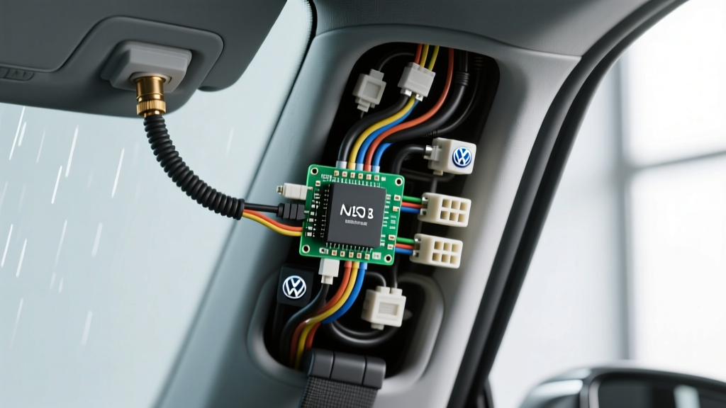
Failure Mode Analysis: The Left A-Pillar Water Pathway
When drivers experience left sunroof open in rain electrical problems, the root cause on the Volkswagen/Audi MQB platform (e.g., Golf Mk7, Audi A3 8V) is rarely the sunroof motor itself. Instead, it is a catastrophic failure of the left-front A-pillar drain routing intersecting with the primary chassis wiring harness. If the left-front sunroof drain tube (P/N 5Q0 877 225) becomes detached from the fender well check-valve, or if the sunroof is left partially open during a squall, precipitation floods the left A-pillar cavity.
Water pools at the base of the A-pillar and breaches the T10o transition connector. Due to capillary action, moisture wicks along the 0.35 mm² (22 AWG) wire insulation directly into the Body Control Module (BCM / J519) located in the left footwell. This specific intrusion pathway triggers cascading LIN and CAN bus faults, immobilizing the sunroof, rain sensor, and left-front door module.
Electrical Architecture & Affected Subsystems
The MQB electrical architecture relies on a centralized J519 BCM to manage low-current switching and local interconnect network (LIN) bus nodes. The sunroof control switch (E325) and the sunroof motor (V1 / J245 control module) communicate via these networks. According to SAE J2602 LIN Bus specifications, the physical layer is highly susceptible to impedance changes caused by conductive fluid bridges.
- Sunroof Switch (E325): Communicates with J519 via LIN Bus 3.
- Sunroof Motor (V1): Requires a dedicated 30A feed (Terminal 30) and communicates via CAN Comfort.
- Left Door Module (J386): Shares the left A-pillar CAN Comfort gateway routing.
Technical Specification: Left A-Pillar & BCM Pinouts
Below is the critical pinout data for the T10o A-pillar connector and the corresponding T52 BCM connector. These are the primary circuits compromised during left-side water intrusion events.
| Pin (T10o) | Pin (T52 BCM) | Wire Color | AWG / mm² | Circuit Function |
|---|---|---|---|---|
| 1 | 17 | Purple/White | 22 AWG (0.35) | LIN Bus 3 (Sunroof Switch / Rain Sensor) |
| 2 | 46 | Orange/Black | 22 AWG (0.35) | CAN Comfort High |
| 3 | 47 | Orange/Brown | 22 AWG (0.35) | CAN Comfort Low |
| 4 | 8 | Brown | 16 AWG (1.5) | Ground (Left Kick Panel Stud) |
| 5 | 52 | Red/Yellow | 14 AWG (2.5) | Terminal 30 (Constant Battery Power) |
Diagnostic Sequence: Capillary Wick & Bus Line Testing
Do not simply replace the sunroof motor if it fails after a rain event. Follow this systematic electrical diagnostic tree to isolate water-induced impedance faults.
Step 1: Visual & Tactile Harness Inspection
Remove the left footwell trim panel and lower dash cover. Locate the J519 BCM. Inspect the T52 connector for green/white copper sulfate corrosion. Even if the connector exterior appears dry, use a thermal camera or carefully feel the harness 6 inches upstream; wicking water often hides inside the PVC insulation jacket. Extracting terminals from the T52 connector requires the specific VAG release tool (P/N T10046 or equivalent micro-pick). Attempting to pry the secondary locking wedge with a standard flathead screwdriver will fracture the PBT-GF30 plastic housing, necessitating a complete BCM pigtail replacement.
Step 2: LIN Bus Voltage Baseline Test
Set your digital multimeter (DMM) to DC Volts. Back-probe Pin 17 of the T52 connector (Purple/White LIN wire) with the ignition ON.
- Normal Recessive State: 11.5V - 12.5V
- Normal Dominant State: Drops to ~1.0V during switch actuation.
- Water Intrusion Fault: Baseline voltage reads between 4.0V and 8.5V. This indicates a resistive short to ground or cross-talk with the CAN-Low circuit due to the conductive water bridge.
Step 3: Insulation Resistance (Megger) Test
Disconnect the battery and unplug the T52 connector. Using a low-voltage insulation tester (do not exceed 50V to protect solid-state BCM diodes), measure resistance between Pin 17 (LIN) and Pin 8 (Ground). A reading below 500 kΩ confirms internal harness wicking and copper oxidation, requiring a harness splice repair.
Step 4: Oscilloscope Differential CAN Bus Analysis
Water ingress into the T10o connector frequently causes intermittent CAN Comfort bus dropouts, resulting in U112300 (Databus Missing Message) codes in the left door module (J386). Connect a dual-channel oscilloscope to Pins 46 (CAN-H) and 47 (CAN-L) at the BCM.
- CAN-High Recessive: 0.0V | Dominant: 3.6V
- CAN-Low Recessive: 5.0V | Dominant: 1.4V
- Water Bridge Artifact: Look for ringing or collapsed differential voltage where the CAN-H and CAN-L waveforms intersect or fail to mirror each other symmetrically. Moisture creates a parasitic capacitance across the twisted pair, degrading the signal rise-time and causing bit-errors that force the BCM to shut down the bus segment.
Remediation & Dielectric Sealing Specifications
Resolving left sunroof open in rain electrical problems requires both mechanical drain clearing and electrical remediation. Reference VW erWin wiring diagrams to confirm exact splice points and harness routing diagrams for your specific VIN.
- Clear the Drain: Use compressed air (max 30 PSI) to clear the left fender well check-valve. Replace the A-pillar hose if the nipple is torn.
- Excise the Wicked Harness: Cut the affected 0.35 mm² wires a minimum of 8 inches upstream from the T52 connector to reach clean, unoxidized copper. If the copper strands show any black or green oxidation, the wire must be cut back further.
- Splice & Seal: Use adhesive-lined heat shrink butt splices rated for 22-18 AWG. Apply a 2:1 shrink ratio to ensure a watertight environmental seal.
- Dielectric Grease Application: Pack the T52 connector cavity with Nyogel 760G or equivalent dielectric grease to displace residual moisture and prevent future galvanic corrosion.
- Ground Stud Torque: Clean the left kick panel M6 ground stud with a wire brush. Re-torque the ground ring terminal to exactly 9 Nm (80 in-lbs) to ensure optimal chassis grounding.
Post-Repair Module Initialization & Basic Settings
Once the wiring is repaired and the water intrusion source is sealed, the sunroof motor (V1) and BCM will likely retain soft-codes for loss of communication. The sunroof will not respond to the one-touch auto-close function until a basic setting adaptation is performed.
- Connect an OEM-level scan tool (e.g., ODIS) or advanced enthusiast tool (VCDS).
- Navigate to Address Module 46 - Central Comfort or 19 - CAN Gateway and clear all stored U-codes.
- Access Address Module FF - Sunroof (or the specific sub-address depending on the exact MQB model year).
- Select Basic Settings -> Normalization / Adaptation.
- Press and hold the physical sunroof switch (E325) in the 'Close' tilt position until the motor completes a full open/close cycle and stops. This forces the Hall-effect sensors inside the V1 motor to relearn the hard-stops and pinch-protection thresholds.
For advanced diagnostic case studies on capillary wicking in European chassis networks, technicians frequently consult archived case files on the International Automotive Technicians Network (iATN), which highlights how intermittent LIN bus faults can mimic failing sunroof initialization switches.