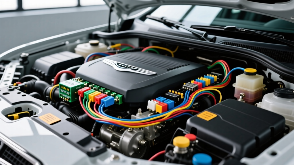
Understanding the LX Platform Multiplex Architecture
When diagnosing Chrysler 300C electrical problems, technicians must look far beyond basic fuse checks and battery load tests. The LX platform (encompassing the 300C HEMI, SRT8, and CRD variants) relies on a highly complex, multiplexed electrical architecture. At the heart of this system is the Totally Integrated Power Module (TIPM), which acts as both a power distribution center and a logic gateway. Furthermore, the vehicle utilizes a dual-bus Controller Area Network (CAN C for high-speed powertrain, CAN B for low-speed interior/body) to facilitate module communication.
Fault-finding on these vehicles requires a systematic approach to voltage drop testing, bus topology verification, and an understanding of specific failure modes inherent to the 300C's wiring harnesses. According to the Chrysler Tech Authority (CTA) diagnostic trees, over 65% of intermittent drivability and no-start conditions on 2005-2010 models stem from TIPM micro-relay degradation or CAN C splice pack corrosion. This guide provides an advanced technical deep dive into resolving these specific architectural vulnerabilities.
The TIPM Internal Relay Failure Matrix
Unlike traditional under-hood fuse boxes, the 300C's TIPM contains surface-mounted PCB micro-relays that are not user-serviceable. The most notorious of these is the internal fuel pump relay, which suffers from contact pitting and solder joint fatigue due to the high inrush current of the 5.7L and 6.1L HEMI fuel pumps.
Symptom-Cause-Fix Decision Tree: Fuel Pump Circuit
- Symptom: Crank, no-start. No fuel pump prime audible. Scan tool shows 'Fuel Pump Relay Control Circuit Open' (P0627).
- Root Cause: Internal TIPM PCB trace failure or micro-relay contact burnout on the fuel pump feed circuit.
- Diagnostic Verification: Probe the external fuel pump feed wire at TIPM Connector C11. If 12V is present at the ASD relay output but missing at the fuel pump feed pin during crank, the internal TIPM relay has failed.
- Advanced Fix: Rather than replacing the $400+ TIPM, install a dealer-approved external bypass harness. This involves tapping the ASD (Auto Shut Down) relay output to externally trigger the fuel pump feed.
TIPM Connector C11 Pinout & Wire Specifications
To execute a voltage drop test or install a bypass harness, you must interface with the 22-way C11 connector. Use a back-probe to avoid terminal splaying. The wire gauges and color codes are critical for proper load handling.
| Pin | Circuit Function | Wire Color | AWG | Test Parameter |
|---|---|---|---|---|
| 13 | ASD Relay Output (Fused B+) | Dark Green / White | 14 AWG | 12.2V - 12.6V (Crank/Run) |
| 16 | Fuel Pump Feed | Dark Green / Light Green | 14 AWG | 0V (Off) / 12.2V (Prime/Run) |
| 20 | Sensor Ground Reference | Black | 14 AWG | < 0.05V Drop to Battery Negative |
| 22 | Fuel Pump PWM Control (if equipped) | Yellow / Dark Blue | 18 AWG | Duty Cycle Signal (Oscilloscope) |
Note: Always verify voltage drop across the C11 connector body itself. A drop greater than 0.15V between the TIPM internal bus bar and the external wire insulation indicates terminal fretting corrosion.
Advanced CAN C Bus Diagnostics (Powertrain)
The CAN C bus operates at 500 kbps and links the PCM, TCM, ABS module, and the Electronic Shift Module (ESM). Because it is a high-speed differential pair, physical layer faults will immediately trigger a 'Bus Off' state, resulting in a no-start condition or severe limp mode. The SAE J2284 standard dictates strict impedance and voltage thresholds for these networks, which must be adhered to during troubleshooting.
OBD-II DLC Breakout & Waveform Expectations
The most accessible diagnostic breakout for the CAN C bus is the Data Link Connector (DLC) located under the driver's dash. You will need a digital multimeter (DMM) for static testing and an oscilloscope for dynamic waveform analysis.
| DLC Pin | Circuit | Wire Color | Resting Voltage (Key Off) | Active Voltage (Key On) |
|---|---|---|---|---|
| 6 | CAN C High (+) | Yellow | 0.0V (Sleep) / 2.5V (Awake) | 2.5V to 3.6V (Recessive to Dominant) |
| 14 | CAN C Low (-) | Green | 0.0V (Sleep) / 2.5V (Awake) | 2.5V to 1.4V (Recessive to Dominant) |
Locating and Testing the CAN C Splice Pack
If your DMM reads 120 ohms across Pins 6 and 14 (with the battery disconnected), you have an open circuit in the bus topology. The CAN C network relies on two 120-ohm terminating resistors (one in the PCM, one in the TCM) wired in parallel to create a 60-ohm baseline. A reading of 120 ohms means one resistor is missing from the circuit.
The most common failure point is the Right Instrument Panel Wire Harness Splice Pack, located behind the right kick panel near the TCM. Moisture ingress from clogged HVAC drain tubes causes the copper splice crimps to oxidize. To repair, cut out the corroded splice block, strip the 18 AWG twisted pair wires, and solder them using marine-grade heat shrink tubing. Do not use standard crimp connectors, as they will introduce signal reflection due to impedance mismatch.
NAG1 Transmission Conductor Plate & TCM Wiring
The 300C utilizes the Mercedes-derived NAG1 (W5A580) 5-speed automatic transmission. A highly specific electrical problem on this platform is the 'Capillary Wicking' failure mode. ATF fluid migrates past the sealing sleeve of the 13-pin circular connector on the transmission case, traveling up the wiring harness via capillary action and directly into the Transmission Control Module (TCM) located in the engine bay.
Inspection and Pinout Verification
Before condemning a NAG1 conductor plate for speed sensor faults (P0720, P0722), you must inspect the TCM connectors. Disconnect the TCM C3 and C4 connectors. If you find red/brown ATF fluid inside the TCM connector cavities, the harness is compromised.
- Disconnect the 13-Pin Connector: Located on the right side of the transmission case. Rotate the locking tab 90 degrees counterclockwise.
- Inspect Pin 1 (Ground - Black) and Pin 2 (Shield): Ensure no fluid is bridging the ground circuit to the high-speed sensor pins.
- Test Speed Sensors (Pins 4 & 5): Using a DMM set to Ohms, measure the internal resistance of the NAG1 speed sensors on the conductor plate. Specification is typically between 800 and 1,200 ohms at 68°F (20°C).
- Replace the Guide Bushing: If fluid is present, you must replace the transmission electrical guide bushing (sealing sleeve) and flush the wiring harness with electrical contact cleaner. In severe cases, the entire engine-to-transmission harness must be replaced to prevent TCM destruction.
For more on transmission-specific electrical faults, the AA1CAR CAN Systems Library provides excellent baseline waveforms for NAG1 solenoid PWM signals, which should show a clean 12V square wave with varying duty cycles depending on line pressure demands.
Parasitic Drain: Isolating the WCM and HFM Modules
The 300C is notorious for parasitic battery drains caused by modules failing to enter the 'Sleep' state. The LX platform requires up to 15 minutes for all CAN B and CAN C modules to power down. A normal sleep-state draw is under 35mA. If your draw remains above 150mA, you have a bus-awake fault.
Voltage Drop Testing Across Fuses
Do not pull fuses one by one to find the draw; this resets module sleep timers and wakes up the network. Instead, use the voltage drop method across the fuse blades.
- Set your DMM to the millivolt (mV) DC scale.
- Wait 20 minutes with the doors locked and the key fob at least 15 feet away from the vehicle to prevent the Wireless Control Module (WCM/SKREEM) from waking up the CAN B bus.
- Probe the two exposed test points on top of each fuse in the rear PDC and interior fuse panel.
- Use Ohm's Law (I = V/R) or a standardized fuse voltage drop chart to calculate the current flow. A 10A Mini fuse showing a 0.4mV drop is flowing approximately 40mA.
Common Culprits: The Hands-Free Module (HFM) located in the trunk lid, and the WCM surrounding the ignition cylinder. If the HFM is keeping the bus awake, check the trunk lid wiring harness flex point for broken 18 AWG ground wires (Black/Light Blue), which cause the module to reset continuously and prevent CAN B sleep.