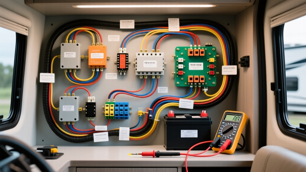
The Hybrid Nature of RV Electrical Systems
Recreational vehicles represent a complex intersection of automotive chassis engineering and residential power distribution. While the chassis relies on standard 12V DC automotive wiring, the coach or 'house' system operates as a hybrid, utilizing both 12V DC battery power and 120V AC shore power. When RV owners begin noticing signs of electrical problems in home coach areas—such as dimming 12V LED fixtures, dead 120V AC outlets while boondocking, or inverter/charger fault codes—the issue rarely lies with the appliance itself. Instead, the culprit is almost always voltage drop, high-resistance ground connections, or undersized DC wiring between the house battery bank and the distribution panel.
As an automotive and RV electrical specialist, I have developed the following step-by-step troubleshooting flow to isolate and resolve high-resistance faults, ground loops, and wiring degradation in motorhome and travel trailer house systems.
Step 1: Inspecting the House Battery Bank and Main Lugs
The house battery bank is the heart of the off-grid electrical system. Most Class A and Class C motorhomes utilize a 4x 6V GC2 deep-cycle flooded lead-acid bank or a parallel/series 12V AGM/LiFePO4 configuration. The interconnects and main feed cables must be sized to handle the continuous DC load of the inverter, which can easily exceed 120 amps.
Terminal Torque and Galvanic Corrosion
The most common cause of inverter low-voltage shutdowns is a high-resistance connection at the battery posts. According to the RV Industry Association (RVIA) guidelines and battery manufacturer specifications, terminal torque is critical:
- Lead-Acid/AGM (3/8-inch Stud): 2/0 AWG copper lugs require 9 to 12 ft-lbs of torque. Under-torquing causes arcing and heat; over-torquing can snap the soft lead posts.
- LiFePO4 Lithium (M8 Terminal): The internal busbars are often soft copper or brass. Torque must be strictly limited to 5 to 7 Nm (approx. 4 to 5 ft-lbs). Over-torquing an M8 bolt on a lithium terminal will strip the internal threads or crush the internal BMS connection.
Pro-Tip: If your RV utilizes flooded lead-acid batteries, the sulfuric acid off-gassing will rapidly oxidize bare copper wire. You must use marine-grade, tinned copper wire (UL 1426 standard) rather than standard automotive primary wire (SAE J1128) for any cabling routed within 18 inches of the battery bank. Tinned copper resists sulfuric corrosion, preventing the green 'copper creep' that increases resistance over time.
Step 2: Voltage Drop Testing the DC Distribution Panel
If the battery terminals are clean and properly torqued, the next step is to test the main positive and negative feed cables running from the battery bank to the DC fuse block (commonly a WFCO or Progressive Dynamics distribution panel).
The Voltage Drop Test Procedure
- Set a True-RMS digital multimeter (e.g., Fluke 87V) to the DC millivolt (mV) scale.
- Connect the red probe to the battery positive post and the black probe to the opposite end of the main positive cable at the DC fuse block input lug.
- Apply a heavy 12V DC load to the system. Turn on the 12V water pump and open a faucet, or turn on the inverter to power a 500W AC load.
- Read the millivolt drop. A healthy 2/0 AWG cable run under 10 feet should show a voltage drop of less than 0.10V (100mV).
- If the drop exceeds 0.20V, you have a high-resistance fault. This is usually caused by a poorly crimped mechanical lug.
Failure Mode Analysis: Many OEM manufacturers use 'hammer crimp' tools or cheap mechanical lugs for 2/0 AWG battery cables. Over years of chassis vibration, these crimps loosen. A proper 2/0 AWG lug must be compressed using a 12-ton hydraulic crimper with hex dies, ensuring a cold-weld gas-tight seal. If you find a voltage drop here, cut off the old lug, strip the cable, and re-terminate with a heavy-duty copper tube lug.
Wire Color Code Collisions: DC vs. AC
When troubleshooting branch circuits at the DC distribution panel, you must understand the severe collision between automotive and residential electrical color codes. This is a massive source of DIY electrocution and blown fuses:
- 12V DC House Wiring (RVIA Standard): White is Ground (-). Black is Positive (+12V).
- 120V AC House Wiring (NEC Standard): White is Neutral. Black is Hot. Green/Bare is Ground.
- Automotive Chassis Wiring: Black is usually Ground. Red is Positive.
If you are tracing a dead 12V water pump circuit and assume the Black wire is ground based on standard automotive knowledge, you will inadvertently short the main 12V positive bus to the chassis, instantly blowing the 30A main DC fuse and potentially frying the pump motor.
Step 3: Inverter/Charger Grounding and Neutral Bonding
Modern pure sine wave inverters (such as the Magnum MS2812 or Victron MultiPlus) require massive DC current to produce 120V AC power. A 2000W inverter pulling from a 12V nominal battery bank will draw roughly 166 amps at peak load, and up to 250 amps during surge startup (e.g., when an AC compressor kicks on).
Chassis Grounding Requirements
The inverter chassis must be bonded to the vehicle frame using a minimum 4 AWG stranded copper wire. This ground wire does not carry the main DC return current (which travels via the massive 2/0 AWG negative cable back to the battery), but it is critical for fault clearing and electromagnetic interference (EMI) shielding.
When attaching the 4 AWG ground ring terminal to the chassis frame rail, you must use a star washer and scrape away all powder coat, e-coat paint, and rust to bare steel. Apply a layer of dielectric grease over the completed connection to prevent galvanic corrosion between the copper lug and the steel frame.
The Neutral-to-Ground Relay Fault
If you are experiencing GFCI outlet trips or 'Ground Fault' errors on your inverter display, the issue is often the internal neutral-to-ground bonding relay. In an RV, the AC Neutral and Ground must only be bonded when the inverter is actively powering the coach (off-grid). When plugged into shore power, the inverter must open this relay, allowing the shore power pedestal to handle the bond. If this relay sticks due to carbon arcing from high-AC-load switching, the RV will display severe signs of electrical problems in home AC outlets, including dangerous stray voltage on the chassis.
RV 12V DC and 120V AC Wiring Specification Chart
| System / Application | Wire Gauge (AWG) | Wire Type Standard | Color Code | Max Continuous Amps |
|---|---|---|---|---|
| Main Battery to Inverter | 2/0 AWG | UL 1426 Tinned Copper | Red (+) / Black (-) | 200A - 250A |
| Battery Interconnects | 2/0 AWG | UL 1426 Tinned Copper | Red (+) / Black (-) | 200A |
| Inverter Chassis Ground | 4 AWG | SAE J1128 Primary | Green or Bare | Fault Current Only |
| DC Branch (Water Pump/Fans) | 12 AWG or 10 AWG | SAE J1128 / UL 1426 | Black (+) / White (-) | 15A - 20A |
| DC Branch (LED Lights) | 14 AWG or 16 AWG | SAE J1128 | Black (+) / White (-) | 10A |
| 120V AC Main Shore Feed | 10 AWG (3-Conductor) | NM-B / THHN | Black(Hot)/Wht(Neu)/Grn(Gnd) | 30A (30 Amp Service) |
Step 4: Parasitic Draw Isolation on the House System
If your house batteries are draining to zero volts within 48 hours of disconnecting shore power, you have a parasitic draw. Unlike a standard automotive chassis where the ignition switch isolates most modules, the RV 'house' system is always live to support the LP gas leak detector, the refrigerator control board memory, and the inverter's internal standby circuitry.
Using a DC Clamp Meter for Non-Intrusive Testing
Never use a standard multimeter in series (the 10A port) to test RV house parasitic draws. The initial surge of the inverter's capacitors charging, or the refrigerator compressor starting, will instantly blow the multimeter's internal fuse. Instead, use a high-resolution DC clamp meter (like the Fluke 325) clamped directly over the main 2/0 AWG negative cable.
- Normal Standby Draw: 0.8A to 1.5A (LP detector, radio memory, CO2 sensor, inverter standby).
- Abnormal Draw (>2.5A): Indicates a stuck relay in the inverter/charger, a shorted diode in the alternator isolation solenoid (BIRD system), or a 12V DC heating element pad left on in the underbelly.
To isolate the draw, systematically pull the automotive-style blade fuses from the DC distribution panel one by one while monitoring the clamp meter. When the amperage drops significantly, you have identified the faulty branch circuit.
Step 5: Thermal Imaging for High-Resistance Connections
When visual inspection and voltage drop testing fail to locate the fault, thermal imaging is the ultimate diagnostic tool for RV electrical systems. Under a sustained 40A DC load (such as running the roof AC unit via the inverter), use a thermal camera (e.g., FLIR TiS20+) to scan the DC bus bars, the Anderson Powerpole SB175 connectors, and the main DC fuse block.
A healthy connection will remain at ambient temperature. A high-resistance crimp or a corroded Anderson Powerpole contact will illuminate as a distinct 'hot spot,' often glowing 20°F to 40°F hotter than the surrounding wire. This localized heat is energy being wasted as resistance, which not only causes voltage drop but poses a severe fire hazard inside the enclosed, insulated walls of an RV coach.
Authoritative References and Standards
For deep-dive schematics and safety standards regarding RV and automotive electrical systems, consult the following resources:
- RV Industry Association (RVIA) - National Fire Protection Association (NFPA) 1192 Standard for Recreational Vehicles, detailing mandatory wire routing, overcurrent protection, and color codes.
- Victron Energy Wiring Unlimited Guide - An industry-standard manual for marine and RV DC/AC inverter wiring, battery bank sizing, and neutral-to-ground bonding protocols.
- SAE International J1128 - Standard for Low Tension Primary Cable used in automotive and RV chassis 12V electrical systems.