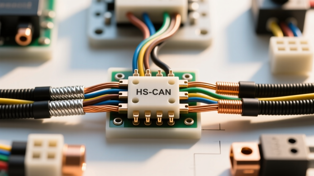
Introduction to Intermittent Network Faults
Tracking down an intermittent car electrical fault in modern multiplexed networks is widely considered one of the most challenging tasks in automotive diagnostics. Unlike a hard failure—such as a severed 12-gauge power wire or a dead battery—intermittent faults on a High-Speed Controller Area Network (HS-CAN) often manifest as fleeting communication dropouts. These dropouts trigger a cascade of U-codes (e.g., U0100 Lost Communication With ECM, U0140 Lost Communication With BCM) and illuminate the malfunction indicator lamp (MIL) without leaving a clear physical trace.
When a technician encounters a network-related car electrical fault, the instinct is often to replace the module that threw the code. However, in over 85% of these cases, the root cause lies in the physical layer of the network: the twisted pair wiring, the termination resistors, or the module ground circuits. This advanced technical deep dive will bypass basic scan tool diagnostics and focus on oscilloscope analysis, physical layer interrogation, and high-resolution voltage drop testing to definitively resolve complex network faults.
The Anatomy of a High-Speed CAN (HS-CAN) Circuit
Before diagnosing a fault, one must understand the strict physical parameters governing the HS-CAN bus. The network relies on a differential signaling method utilizing an unshielded twisted pair (UTP) of wires. According to the SAE J2284-2 Standard, the physical layer must maintain specific impedance, capacitance, and voltage thresholds to prevent signal reflection and electromagnetic interference (EMI).
HS-CAN Physical Layer Specifications
| Parameter | Specification / Value | Diagnostic Tolerance |
|---|---|---|
| Wire Gauge & Type | 0.5 mm² (20 AWG) Unshielded Twisted Pair | Must not be untwisted for more than 50mm during repair |
| Twist Rate | 33 to 50 twists per meter | Crucial for common-mode noise rejection |
| Termination Resistance | 120 Ω at each end of the bus (Total: 60 Ω) | Acceptable range: 58 Ω to 62 Ω measured at DLC |
| CAN-H Recessive / Dominant | 2.5V / 3.5V | ± 0.2V variance tolerated by most transceivers |
| CAN-L Recessive / Dominant | 2.5V / 1.5V | ± 0.2V variance tolerated by most transceivers |
| OBD-II DLC Pinout | Pin 6 (CAN-H) / Pin 14 (CAN-L) | Pins 4 and 5 must have < 50mV drop to battery negative |
When a car electrical fault causes the termination resistance to drift outside the 58–62 Ω window, signal reflections occur. These reflections corrupt the data frame's Cyclic Redundancy Check (CRC), forcing the transmitting module to continuously rebroadcast the message, eventually leading to a bus-off state and a U-code.
Advanced Diagnostic Decision Tree: Intermittent Car Electrical Fault
When an intermittent U-code is stored, follow this systematic decision tree to isolate the physical layer fault.
- Step 1: Gateway Interrogation. Connect a factory-level bidirectional scan tool. Access the Gateway Module (or Central Gateway). Check the CAN bus topology map. Which specific module is dropping off the network? Is it dropping alone, or is an entire branch of the network failing simultaneously?
- Step 2: DLC Resistance Check (Key Off). Turn the ignition OFF and wait 60 seconds for modules to enter sleep mode. Measure resistance between OBD-II DLC Pin 6 and Pin 14.
- If 120 Ω: One termination resistor is open. (Proceed to locate the missing 120 Ω resistor, typically inside the ECM or BCM).
- If 0 Ω or < 10 Ω: CAN-H and CAN-L are shorted together.
- If 60 Ω: Termination is physically intact. The fault is likely a voltage bias issue, high-resistance ground, or internal transceiver failure. Proceed to Step 3.
- Step 3: Oscilloscope Bias Voltage Test (Key On, Engine Off). A Digital Multimeter (DMM) is insufficient for capturing microsecond transients. Connect a dual-channel oscilloscope to Pins 6 and 14. Observe the recessive state bias voltage. Both lines should rest at exactly 2.5V. If CAN-H rests at 2.6V and CAN-L rests at 2.3V, you have identified a car electrical fault caused by a high-resistance short to a 5V reference circuit or a failing module pulling the bus bias off-center.
Phase 2: Capturing the Intermittent Dropout
To catch an intermittent car electrical fault in the act, you must manipulate the harness while monitoring the oscilloscope. Set the scope timebase to 20 µs/div and voltage scale to 2V/div. Use a trigger condition set to drop below 2.0V on the CAN-L channel. While the scope is armed, physically manipulate the harness near the suspected module, the splice packs, and the firewall bulkhead connectors. If the waveform collapses or spikes, you have isolated the physical location of the fault.
Deep Dive: Hidden High-Resistance Grounds
A frequently overlooked cause of network-related electrical faults is a high-resistance ground at the module itself. A CAN transceiver requires a rock-solid ground reference to accurately interpret the differential voltage between CAN-H and CAN-L. If the module's ground circuit has 500 mV of unwanted resistance, the transceiver's internal logic will misinterpret recessive and dominant states, resulting in corrupted data frames.
According to diagnostic procedures outlined by MOTOR Information Systems, measuring a ground circuit with an ohmmeter is a flawed practice. An ohmmeter uses less than 10 milliamps of test current. A corroded ground stud might pass 10mA perfectly, showing 0.2 Ω on your DMM, but when the module draws its normal operating current of 2.5 Amps, Ohm's Law (V = I x R) dictates that a 2.5A load across a degraded connection will cause a massive voltage drop, resetting the microprocessor.
Voltage Drop Testing Protocol for Module Grounds
| Test Point A | Test Point B | Maximum Allowable Drop | Corrective Action if Failed |
|---|---|---|---|
| Battery Negative Post | Module Ground Pin (Harness Side) | 50 mV (0.050V) with Key On | Clean G101/G200 ground stud to bare metal. Torque to 10 Nm (89 lb-in). |
| Battery Negative Post | Engine Block Ground Strap | 100 mV (0.100V) during Crank | Replace 4 AWG braided ground strap. Apply di-electric grease to terminals. |
| Module Power Pin | Battery Positive Post | 100 mV (0.100V) with Key On | Check under-hood fuse box bus bar for corrosion or loose B+ cable nut. |
Crucial Technique Note: Always place your DMM probes directly on the metal terminal of the connector and the battery post. Never measure from the wire insulation or the battery clamp (measure directly to the lead post). A loose battery clamp can introduce a false car electrical fault reading by adding the resistance of the clamp-to-post interface into your measurement.
Real-World Case Study: Capillary Wicking in Splice Pack S302
Consider a scenario involving a late-model European sedan presenting an intermittent U0140 (Lost Communication with Body Control Module). The fault only occurred during heavy rain or high humidity. Initial diagnostics revealed 60 Ω of termination resistance at the DLC, and oscilloscope captures showed clean square waves with proper 2.5V bias during dry conditions.
The breakthrough occurred when a technician utilized a thermal chamber to simulate high humidity. As moisture levels rose, the CAN-L waveform began to exhibit severe ringing and voltage sag. Tracing the wiring diagram revealed Splice Pack S302, located deep within the driver-side A-pillar kick panel. Upon cutting back the loom, the technician discovered that water had entered a frayed section of the trunk lid harness months prior. Through capillary action, the water had wicked its way down the 20 AWG copper strands, eventually reaching the S302 splice pack. The moisture created a high-resistance, intermittent short between the CAN-L wire and the adjacent shield drain wire.
The repair required cutting out the corroded splice pack, stripping back the wires to clean, un-oxidized copper, and utilizing sealed, adhesive-lined heat shrink butt connectors (meeting NHTSA and OEM wiring repair standards) to prevent future moisture ingress. This case perfectly illustrates why diagnosing a complex car electrical fault requires an understanding of environmental variables and physical wire anatomy, not just the ability to read a scan tool.