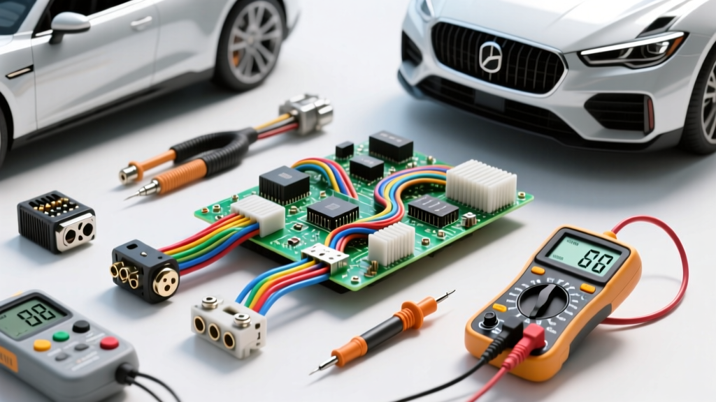
The Evolution of Diagnostic Hardware
When diagnosing automotive electrical problems, the gap between a "parts replacer" and a true diagnostic technician is defined entirely by their test equipment. Modern vehicles have largely abandoned simple switched 12V circuits in favor of multiplexed networks (CAN, LIN, FlexRay) and Pulse Width Modulated (PWM) actuators. Attempting to troubleshoot a 2018+ GM K2XX platform or a Ford EcoBoost engine management system with a basic incandescent test light will not only yield inaccurate data but can actively destroy sensitive solid-state control modules.
This guide compares the three primary categories of diagnostic hardware—Digital Multimeters (DMMs), Active Circuit Testers, and Automotive Oscilloscopes—to help you select the right tool for specific electrical fault-finding scenarios.
Digital Multimeters: The Fluke 88V Benchmark
The Digital Multimeter remains the foundational tool for diagnosing automotive electrical problems. However, not all DMMs are created equal. The Fluke 88V Automotive Multimeter is widely considered the industry standard due to its specialized automotive functions and critical safety ratings.
Key Specifications and Safety
- Safety Rating: CAT III 1000V / CAT IV 600V. This is non-negotiable when testing high-energy circuits in hybrid/EV battery packs or heavy-duty alternator outputs.
- Automotive Metrics: Built-in RPM (via inductive pickup or tach signal), dwell angle, and duty cycle percentage.
- Input Protection: High-energy 10A fused inputs prevent catastrophic meter failure if a technician accidentally tests voltage while the leads are in the amp jacks.
- Min/Max Recording: Crucial for capturing intermittent voltage drops across a 10 AWG starter feed cable during engine cranking.
Best Use Case: Voltage drop testing, parasitic draw measurement (after module sleep), and verifying sensor reference voltages (5V VREF).
Active Circuit Testers: Power Probe III vs. Logic Probes
Active circuit testers, most notably the Power Probe III, allow technicians to supply power or ground directly to a component while simultaneously monitoring circuit voltage. While incredibly fast for testing window motors, relays, and fuel pumps, they carry severe risks if misused during ECU-level diagnostics.
The Danger of Active Probing
When diagnosing automotive electrical problems involving Engine Control Modules (ECMs) or Transmission Control Modules (TCMs), applying 12V to a circuit designed for a 5V logic signal will instantly fry the internal driver transistor. For example, backfeeding a 5V Hall-effect crankshaft position sensor signal wire (typically 18 AWG or 20 AWG) with a Power Probe will destroy the ECM's internal pull-up resistor.
- Pros: Instantly identifies open circuits, bad grounds, and failed actuators without needing a wiring diagram for simple 12V loads.
- Cons: High risk of ECM damage; cannot read data bus communication or PWM duty cycles accurately.
Best Use Case: Bench-testing removed components, actuating relays, and testing high-amperage accessory circuits (e.g., seat heaters, cooling fan primary feeds).
Automotive Oscilloscopes: Time-Domain Analysis
For advanced network and actuator diagnostics, a multimeter is too slow. The PicoScope 4425A automotive oscilloscope samples electrical signals millions of times per second, translating invisible voltage fluctuations into visible waveforms.
Capturing CAN Bus and PWM Signals
When diagnosing automotive electrical problems related to communication networks, a scope is mandatory. A Controller Area Network (CAN) bus operates on differential voltage. CAN High typically rests at 2.5V and spikes to 3.5V, while CAN Low rests at 2.5V and drops to 1.5V. A standard DMM will only display an averaged, useless voltage of roughly 2.5V. An oscilloscope reveals the exact square-wave architecture, allowing you to spot termination resistor failures (which double the voltage amplitude) or short-to-ground faults.
Best Use Case: CAN/LIN bus decoding, verifying injector peak-and-hold current waveforms, and analyzing variable valve timing (VVT) solenoid PWM signals.
Tool Selection Matrix
| Diagnostic Tool | Primary Application | Risk to ECM/TCM | Signal Type Handled |
|---|---|---|---|
| Fluke 88V DMM | Voltage drop, parasitic draw, VREF verification | Low (if fused properly) | DC Voltage, Resistance, Duty Cycle |
| Power Probe III | Actuator testing, relay jumping, ground verification | Extremely High | High-current 12V DC loads only |
| PicoScope 4425A | CAN bus faults, injector current, PWM fan control | None (Passive testing) | High-frequency AC/DC, Differential |
| Logic Probe (LED) | Basic injector pulse, ignition coil trigger verification | Low | Low-current switched grounds |
Case Study: Diagnosing a GM PWM Cooling Fan Circuit
To illustrate tool selection, let us examine a common fault: a cooling fan that runs continuously at high speed on a 2017 Chevrolet Silverado 5.3L (K2XX platform). In this system, the ECM does not simply switch a relay. It outputs a Pulse Width Modulated (PWM) signal to a dedicated Fan Control Module.
Circuit Specifications
- Power Feed: 10 AWG Red wire (Battery positive, fused at 40A).
- Ground: 10 AWG Black wire (Chassis ground G108).
- PWM Control Signal: 18 AWG Dark Blue wire (Circuit 1320), originating from ECM Connector X2, Pin 42.
The Diagnostic Process
- Step 1: The DMM Check. Using the Fluke 88V, you measure the 10 AWG power and ground. You read 12.4V at the module and a voltage drop of 0.02V across the ground circuit. The high-amperage supply is healthy.
- Step 2: The Signal Verification. You connect the DMM to the 18 AWG Dark Blue control wire. With the engine cold, the DMM reads a steady 12V (the default fail-safe high-speed mode). This indicates the ECM is either commanding high speed due to a sensor fault, or the control wire is shorted to voltage.
- Step 3: The Oscilloscope Confirmation. To definitively diagnose the PWM signal without piercing the wire, you backprobe the ECM X2 connector using a specialized Delphi Weather-Pack probe pin. You connect the PicoScope (set to 20V/div and 50ms/div). The waveform shows a flat 12V line with zero PWM activity, confirming the ECM has lost the ability to modulate the signal, likely due to an internal driver fault or a failed A/C pressure sensor reading causing a fail-safe trigger.
Attempting to use a Power Probe on this 18 AWG Dark Blue wire to "force" the fan on would bypass the PWM module entirely and could backfeed voltage into ECM Pin 42, resulting in a $1,200 ECM replacement.
Connector Preservation and Backprobing Standards
A critical, often overlooked aspect of diagnosing automotive electrical problems is terminal preservation. Modern vehicles rely on sealed connector systems like the TE Connectivity Deutsch DT series and Delphi Weather-Pack. These terminals feature delicate beryllium-copper spring fingers that ensure water-tight seals and low-resistance contact.
Never use paperclips, sewing needles, or standard multimeter leads to backprobe a connector. Doing so will splay the terminal fingers, leading to micro-arcing, localized heat buildup, and eventual melting of the plastic connector housing. Always use dedicated backprobe pins (such as the OTC 4488 kit or specific OEM terminal adapters) that match the exact gauge of the terminal cavity (e.g., 1.5mm, 2.8mm, or 4.8mm blade widths). For sealed connectors, use piercing probes only on non-communication, high-amperage wires (12 AWG or larger), and always seal the puncture with liquid electrical tape or silicone dielectric grease to prevent copper oxidation.
Summary: Building Your Diagnostic Arsenal
There is no single "magic tool" for automotive electrical diagnostics. A master technician relies on a synergistic approach: using the SAE J1939 compliant oscilloscope to visualize network integrity, the high-impedance DMM to verify power and ground integrity via voltage drop testing, and active testers strictly isolated to high-current accessory loads. By matching the tool to the specific circuit architecture, you ensure accurate diagnostics and protect the vehicle's sensitive solid-state electronics.