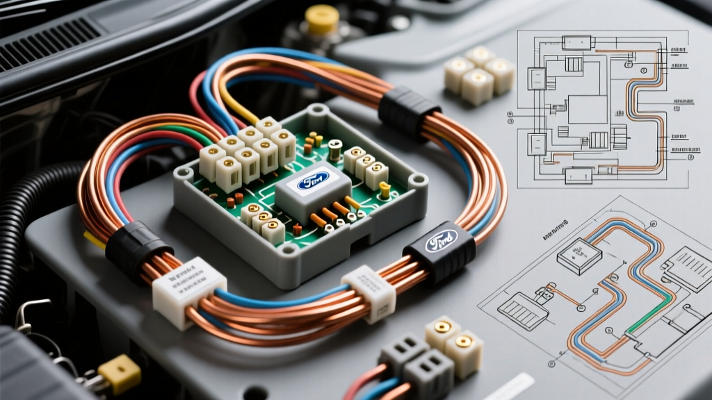
The True Cost of Diagnosing Ford Explorer Electrical Problems
Owning a Ford Explorer often means eventually dealing with complex electrical gremlins, particularly in the U502 (2011–2019) and U625 (2020–Present) platforms. Modern Explorers feature heavily multiplexed networks with up to 15+ modules communicating over High-Speed (HS-CAN) and Medium-Speed (MS-CAN) Controller Area Networks. When Ford Explorer electrical problems arise—ranging from parasitic battery drains to complete CAN-bus lockouts—the cost of diagnosis can quickly eclipse the cost of the repair if you rely solely on dealership labor rates.
Dealerships typically charge $150 to $225 per hour for electrical diagnostic time, and pinpointing a faulty Body Control Module (BCM) or a chafed MS-CAN wire can easily consume 2 to 4 hours of labor. However, by investing in the right automotive-grade diagnostic tools, DIYers and independent technicians can perform these diagnostics for a fraction of the cost. This guide breaks down the exact tool requirements, hardware specifications, and cost-to-benefit analysis of diagnosing Ford Explorer wiring faults at home versus the dealer.
Essential Diagnostic Tools & Hardware Specifications
Standard consumer-grade tools are insufficient and potentially dangerous to Ford’s sensitive multiplex networks. To properly troubleshoot Explorer electrical issues, your toolkit must meet strict automotive specifications.
Multimeter Requirements: Impedance and Fusing
When probing CAN-bus lines or module reference voltages, using a cheap multimeter with low input impedance can backfeed voltage and fry a Ford HS-CAN transceiver. You must use a Digital Multimeter (DMM) with a minimum 10 Megohm (10MΩ) input impedance. Furthermore, the meter must feature high-energy HRC (High Rupturing Capacity) fuses rated for at least 10A and 15A to prevent catastrophic meter failure if you accidentally probe a voltage source while in continuity/amperage mode.
- Recommended Tool: Fluke 88V Automotive Multimeter.
- Cost: ~$450 - $500.
- Why it matters: The Fluke 88V features specialized automotive test modes, including RPM inductive pickups, duty cycle measurement for Ford PCM injector pulses, and min/max recording to catch intermittent voltage drops on the alternator sense wire. For a budget alternative, the Power Probe PDMMK1 (~$250) offers adequate impedance for basic 12V and ground testing, though it lacks the oscilloscope-level precision of the Fluke.
According to Fluke's Automotive Multimeter Guide, ensuring your test leads are silicone-insulated and rated for CAT III or CAT IV is critical when working near the Explorer's high-amperage Smart Junction Box (SJB).
Ford-Specific Scan Tools & OBD-II Pinouts
Generic OBD-II scanners only read the Powertrain Control Module (PCM) via the HS-CAN bus. To diagnose Ford Explorer electrical problems related to the BCM, Instrument Panel Cluster (IPC), or Restraints Control Module (RCM), you must access the MS-CAN bus. This requires a specialized adapter capable of toggling between the two networks or a dual-CAN interface.
The SAE J1962 OBD-II Standard dictates the physical connector, but Ford utilizes proprietary pin assignments for its dual-network architecture:
- Pin 6: CAN-H (HS-CAN) — Wire Color: White/Blue (20 AWG)
- Pin 14: CAN-L (HS-CAN) — Wire Color: White/Brown (20 AWG)
- Pin 3: CAN-H (MS-CAN) — Wire Color: White/Green (20 AWG)
- Pin 11: CAN-L (MS-CAN) — Wire Color: White/Violet (20 AWG)
- Pin 16: Battery + (Red, 14 AWG)
- Pins 4 & 5: Signal & Chassis Ground (Black, 14 AWG)
Tool Requirement: An OBDLink EX or vLinker FS cable paired with FORScan software. These adapters feature internal relays that automatically toggle between Pins 6/14 and Pins 3/11 based on the module being polled. Building a manual toggle switch costs about $15 in electronics components, but the time lost manually switching networks makes the $100-$130 investment in an auto-switching cable a mandatory ROI for Ford diagnostics.
Common Ford Explorer Wiring Faults & Repair Cost Matrix
Below is a breakdown of the most frequent electrical faults across the Explorer lineup, contrasting the DIY tool and material costs against typical dealership repair invoices.
| Fault / Symptom | Root Cause & Wiring Details | DIY Tool & Material Cost | Dealer Repair Cost |
|---|---|---|---|
| Parasitic Battery Drain (2011-2019) | Internal BCM relay failure or water intrusion at Connector C2280E. Draw exceeds 800mA on the 14 AWG Yellow/Red battery feed. | $45 (Multimeter) + $150 (Used BCM) | $250 Diag + $650 Module + $200 Labor = $1,100+ |
| Alternator Overcharging / Dash Warning | Voltage drop on the 18 AWG Yellow/Black (Y/BK) sense wire between PCM Pin 15 and Alternator connector due to corrosion. | $25 (Adhesive Heat Shrink & 18 AWG Wire) | $180 Diag + $150 Harness Repair = $330+ |
| MS-CAN Lockout (Radio/HVAC Dead) | Chafed MS-CAN wires (White/Green, White/Violet) under the driver's seat rubbing against the seat track. | $15 (Solder Seal Connectors & Loom) | $225 Diag + $150 Labor = $375+ |
| Erratic Fuel Gauge / IPC | Corroded G101 or G201 ground points in the front wheel wells causing floating ground reference on the 20 AWG signal wire. | $12 (Dielectric Grease & Sandpaper) | $150 Diag + $120 Ground Cable = $270+ |
Step-by-Step Tool ROI: Tackling the BCM Parasitic Draw
One of the most notorious Ford Explorer electrical problems is the parasitic draw caused by the Body Control Module (BCM) located in the left kick panel (U502 platform). If your Explorer battery dies after 2–3 days of sitting, follow this diagnostic sequence to validate the fault without throwing parts at the vehicle.
Step 1: The Voltage Drop Test (Non-Invasive)
Never pull fuses to find a parasitic draw in a modern Ford; this wakes up modules and resets the sleep timer. Instead, use your DMM in millivolt (mV) mode to measure the voltage drop across the Smart Junction Box (SJB) fuses.
- Ensure all doors are closed (use a piece of tape to depress the latch if necessary) and the key is out of the ignition.
- Wait 45 minutes for the Ford network to enter "Sleep Mode".
- Probe both sides of the BCM memory fuses (typically Fuse 15, 20A, and Fuse 21, 10A in the interior SJB).
- Use the Ohm's Law chart (specifically for standard automotive Mini/ATO fuses) to convert the mV reading to amperage. A reading of 15mV across a 20A fuse equates to roughly 2.5 Amps—a massive draw indicating a stuck internal BCM relay.
Step 2: Isolating the BCM Feed
If the SJB test points to the BCM, locate the BCM Connector C2280E. The primary battery feed is Pin 1 (Yellow/Red, 14 AWG). Disconnect the negative battery terminal, insert your multimeter (set to 10A) in series with Pin 1, and reconnect the battery. If the draw remains above 50mA after the sleep cycle, the BCM is internally faulted or has suffered water intrusion from a clogged cowl drain. Replacing the BCM requires a FORScan "As-Built" data restore, which is free via software but impossible with a generic code reader.
Alternator Sense Wire & PCM Communication (2006-2010 U251)
For owners of the previous generation U251 Explorer, a common electrical problem involves the charging system. The PCM monitors battery voltage via a dedicated 18 AWG sense wire (Yellow/Black). If this wire suffers a voltage drop due to corrosion at the alternator pigtail (Motorcraft WPT-1246), the PCM incorrectly commands the alternator's internal voltage regulator to overcharge, often boiling the battery or triggering the battery warning light.
The Fix: Perform a voltage drop test on the Y/BK wire with the engine running. If the voltage at the alternator connector is more than 0.2V lower than the voltage at the battery positive terminal, cut out the corroded section. Splice in a new 18 AWG wire using adhesive-lined heat shrink connectors (never use crimp caps or electrical tape under the hood) and apply dielectric grease to the alternator connector pins.
Conclusion: Sourcing and Final ROI
Diagnosing Ford Explorer electrical problems requires an upfront investment in high-impedance testing equipment and dual-CAN software interfaces. A complete DIY setup—including a quality DMM, an auto-switching FORScan cable, and a basic wiring repair kit—will cost between $500 and $750. Considering a single dealership diagnostic and module replacement easily exceeds $1,200, the DIY tooling pays for itself on the very first major electrical fault. Always reference factory wiring diagrams for exact pinouts, as wire colors and SJB fuse assignments can vary slightly between the XLT, Limited, and Platinum trim levels.