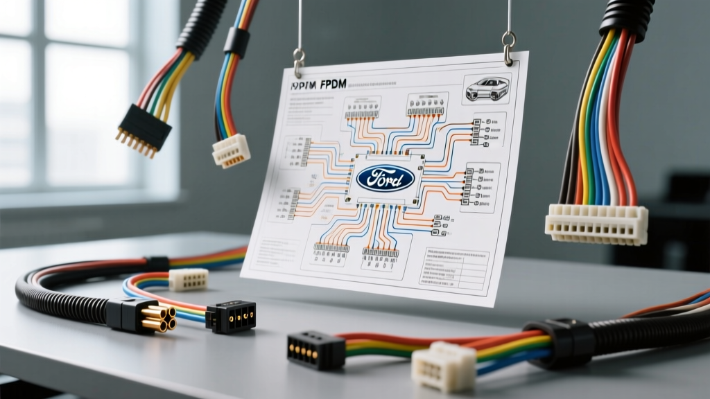
Introduction to Schematic-Driven Diagnostics
Reading a wiring diagram is only the first step in modern automotive troubleshooting. The true challenge lies in translating the two-dimensional schematic into physical, real-world measurements. When dealing with complex, module-driven circuits, guessing is not an option. You must systematically apply auto electrical diagnostic tools to specific circuit nodes to isolate faults without causing collateral damage to sensitive control modules. In this complete wiring diagram walkthrough, we will dissect a modern Ford Fuel Pump Driver Module (FPDM) circuit. We will map the schematic to the physical harness, select the appropriate diagnostic instruments, and execute a step-by-step verification process using specific wire colors, AWG ratings, and voltage parameters.
The FPDM Circuit: Schematic Matrix and Pinout
The FPDM is a pulse-width modulated (PWM) controller that varies the voltage supplied to the fuel pump based on engine demand. Unlike older return-style systems with a simple relay, the FPDM requires precise power, ground, and network communication. Before touching your auto electrical diagnostic tools, you must understand the connector architecture. The FPDM typically utilizes a 6-pin sealed Metripack-style connector (often designated as C402 in Ford service literature).
| Pin | Circuit Function | Wire Color | Wire Gauge (AWG) | Destination / Source |
|---|---|---|---|---|
| 1 | FPDM Main Power | Light Green/Yellow (LG/YE) | 12 AWG | Fuel Pump Relay / B+ |
| 2 | FPDM Main Ground | Black/White (BK/WH) | 12 AWG | Chassis Ground (G101) |
| 3 | PCM Command (PWM) | White/Black (WH/BK) | 18 AWG | Powertrain Control Module |
| 4 | FPDM Feedback | Green/Orange (GN/OG) | 18 AWG | Powertrain Control Module |
| 5 | Fuel Pump Power Out | Pink/Black (PK/BK) | 14 AWG | In-Tank Fuel Pump Motor |
| 6 | Fuel Pump Ground Out | Brown/Yellow (BN/YE) | 14 AWG | Fuel Pump Motor Ground |
Selecting the Right Auto Electrical Diagnostic Tools
Not all tools are created equal. A standard digital multimeter (DMM) is excellent for static voltage and resistance checks, but it is virtually useless for analyzing dynamic PWM signals or high-speed data networks. For this walkthrough, we will utilize a professional-grade DMM with min/max recording, a 4-channel automotive oscilloscope, and an AC/DC current clamp. Relying on the correct auto electrical diagnostic tools ensures you are viewing the electrical reality of the circuit, not an averaged-out approximation.
Digital Multimeter (DMM) vs. Automotive Oscilloscope
A DMM samples voltage a few times per second. If you probe Pin 3 (WH/BK) with a DMM, you will see an erratic, fluctuating voltage reading that tells you nothing about the signal's integrity. An oscilloscope, however, samples millions of times per second, allowing you to visualize the exact duty cycle, frequency, and voltage plateau of the PCM's command signal. For a complete diagnostic walkthrough, the oscilloscope is mandatory for the control side of the circuit.
Step-by-Step Diagnostic Walkthrough
Phase 1: Power and Ground Integrity (Voltage Drop)
Before analyzing the complex PWM signals, we must verify the foundational power and ground circuits. A module cannot command a fuel pump if its own power supply is compromised. We will perform a dynamic voltage drop test on Pins 1 and 2.
- Setup: Set your DMM to DC Volts. Connect the red lead to the battery positive post and the black lead to Pin 1 (LG/YE, 12 AWG) at the FPDM harness connector using a back-probe or breakout box.
- Load the Circuit: Crank the engine or command the fuel pump ON via a bidirectional scan tool. The circuit must be under load to reveal high-resistance faults.
- Evaluate: A healthy 12 AWG power wire should exhibit a voltage drop of less than 0.15V. If your DMM reads 0.45V or higher, you have excessive resistance. This is commonly caused by corrosion at the Fuel Pump Relay socket or a failing inertia switch.
- Ground Test: Move the DMM black lead to the battery negative post and the red lead to Pin 2 (BK/WH, 12 AWG). Under load, the ground side voltage drop must also remain below 0.15V. High resistance on the 12 AWG ground wire will cause the FPDM to overheat and trigger a diagnostic trouble code (DTC) such as P1233 (Fuel System Disabled or Offline).
Phase 2: PCM Command Signal Verification (PWM)
With power and ground confirmed, we move to the control circuit. The PCM sends a PWM signal on Pin 3 (WH/BK, 18 AWG) to dictate fuel pressure. According to Pico Automotive Waveform Library standards, analyzing this requires an oscilloscope.
- Setup: Connect Channel A of your oscilloscope to Pin 3 (WH/BK) using a piercing probe or breakout box. Set the timebase to 20ms/div and the voltage scale to 5V/div.
- Capture: Start the engine. You should see a square wave pattern. The signal will toggle between 0V and approximately 12V (battery voltage).
- Measure Duty Cycle: Use the scope's cursors to measure the duty cycle. At idle, the PCM typically commands a 20% to 30% duty cycle. Under heavy acceleration, the duty cycle should ramp up to 70% to 85% to maximize fuel pump speed.
- Verify Frequency: The frequency of the WH/BK wire should remain relatively stable, typically between 100Hz and 400Hz depending on the specific OEM calibration. If the waveform shows sloped edges (RC decay) instead of sharp vertical transitions, you have excessive capacitance or a short-to-ground degrading the 18 AWG signal wire.
Phase 3: Fuel Pump Load and Current Draw
The final step in our walkthrough is verifying the output side of the FPDM (Pins 5 and 6). Instead of relying solely on voltage, we will measure the physical work being done by the fuel pump motor using a current clamp.
- Setup: Clamp your AC/DC current probe around the Pin 5 (PK/BK, 14 AWG) output wire. Route the BNC cable into Channel B of your oscilloscope.
- Capture: Start the engine. A healthy in-tank fuel pump will draw between 6 to 10 amps at idle, depending on the specific vehicle application and fuel pressure requirements.
- Analyze the Waveform: The current waveform will not be a flat line. You will see high-frequency ripple caused by the commutator and brushes inside the DC motor. Missing or flat spots in the current ripple indicate worn brushes or a dead commutator bar inside the pump assembly, even if the average amperage appears normal.
Real-World Failure Modes and Harness Chafing
When executing this walkthrough, technicians frequently encounter physical harness failures that mimic internal module faults. The FPDM is often mounted on the frame rail or near the spare tire well, exposing the 12 AWG and 18 AWG wiring to the elements. A notorious failure point is the chafing of the WH/BK (PWM command) and GN/OG (feedback) wires against the frame rail bracket. Because these are 18 AWG wires, even minor insulation wear will cause a short-to-ground, pulling the PCM's 12V driver low and setting a P1237 (Fuel Pump Secondary Circuit Malfunction) code. Always physically inspect the harness routing when the schematic indicates the circuit passes through a high-vibration, exposed chassis area.
Common Misdiagnoses When Ignoring the Schematic
Without a systematic walkthrough using the correct auto electrical diagnostic tools, technicians often fall into the trap of 'parts swapping.' A common misdiagnosis involves replacing the fuel pump when the actual fault is a degraded 14 AWG PK/BK output wire. If the 14 AWG wire suffers from internal copper stranding corrosion (green death), it will create a voltage drop between the FPDM and the pump. The scan tool will show that the PCM is commanding 80% duty cycle, and the FPDM is outputting 12V, but the pump only receives 8V due to the wire resistance. The pump runs slow, fuel pressure drops, and the technician replaces a perfectly good pump assembly. By following the schematic and performing voltage drop tests on the output side (Pin 5 to the pump positive terminal), this costly misdiagnosis is entirely avoided.
Conclusion
Mastering automotive electrical repair requires more than just reading a wiring diagram; it requires knowing exactly where and how to apply your auto electrical diagnostic tools to validate the schematic in the real world. By breaking down the FPDM circuit into power, control, and load phases, and utilizing DMMs and oscilloscopes to measure specific 12, 14, and 18 AWG circuits, you can confidently isolate faults. For further reading on module communication standards and network topologies, refer to the SAE J1939 Network Standards and official Ford Motor Company Service Manuals. Always let the schematic guide your tools, and let the tools reveal the truth of the circuit.