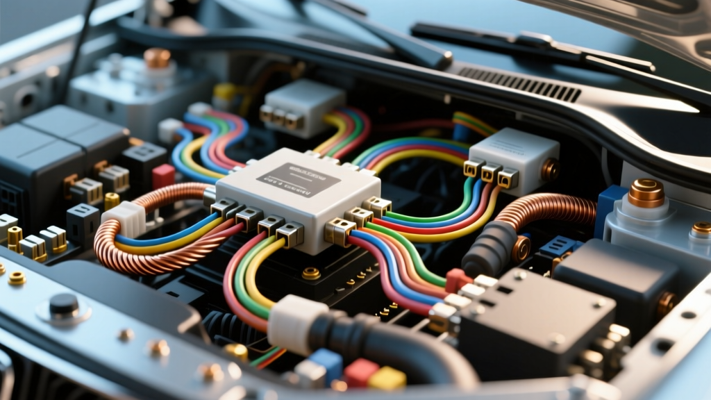
The Paradigm Shift in Automotive Electrical Issues with Car Networks
Modern vehicles do not rely on simple point-to-point wiring harnesses; they operate on complex multiplexed localized area networks. When technicians encounter intermittent electrical issues with car networks, the root cause is rarely a simple broken wire or a dead battery. Instead, the fault usually lies within the Controller Area Network (CAN) bus topology, module sleep-state failures, or high-frequency signal degradation. Diagnosing these advanced electrical issues with car systems requires moving beyond basic multimeters and embracing oscilloscope waveform analysis, differential voltage testing, and precise network termination verification.
In this advanced technical deep dive, we will dissect the High-Speed GMLAN (HS-GMLAN) architecture, analyze differential waveform faults, and outline systematic procedures for isolating multiplexed parasitic draws that drain batteries overnight.
High-Speed CAN (HS-CAN) Topology and Termination Specifications
The HS-CAN bus operates at up to 500 kbps, utilizing a differential signaling method to reject electromagnetic interference (EMI). The physical layer consists of a twisted pair of wires (typically 20 AWG / 0.5 mm²) with a twist rate of one twist every 25-50mm. According to ISO 15765-4 and SAE J1939 standards, the network requires two 120-ohm termination resistors located at the extreme ends of the bus—usually integrated into the Engine Control Module (ECM) and the Body Control Module (BCM). When measured in parallel at the OBD-II Data Link Connector (DLC), a healthy network must yield exactly 60 ohms.
| Parameter | CAN-High (DLC Pin 6) | CAN-Low (DLC Pin 14) | Differential Spread |
|---|---|---|---|
| Wire Color (GM HS-GMLAN) | Dark Green (D-GN) | Light Green (L-GN) | N/A |
| Recessive State (Idle) | ~2.50V | ~2.50V | 0.00V |
| Dominant State (Active) | ~3.50V | ~1.50V | 2.00V |
| Max Allowable Resistance | < 1.0 Ω to ECM | < 1.0 Ω to ECM | 60 Ω ± 5 Ω (Total) |
If your multimeter reads 120 ohms at the DLC, one of the terminating modules is offline, disconnected, or suffering from an internal resistor failure. A reading of 40 ohms indicates an unauthorized or aftermarket module with an extra termination resistor has been spliced into the network, causing signal reflection and data corruption.
Advanced Oscilloscope Diagnostics for Differential Signals
A Digital Multimeter (DMM) is fundamentally inadequate for diagnosing high-speed CAN faults because its sampling rate cannot capture nanosecond-level voltage spikes or EMI intrusion. To properly diagnose electrical issues with car CAN networks, a digital storage oscilloscope (DSO) with a minimum bandwidth of 100 MHz and a sampling rate of 1 GS/s is mandatory.
Interpreting the Waveform
Connect Channel A to CAN-H (Pin 6) and Channel B to CAN-L (Pin 14). Set the timebase to 20 µs/div and voltage scale to 2V/div. Trigger on the rising edge of Channel A. A healthy waveform will display perfect symmetry: as CAN-H steps up to 3.5V, CAN-L must step down to 1.5V simultaneously. The math channel (Ch A - Ch B) should yield a clean 2.0V peak-to-peak differential square wave.
Common waveform anomalies include:
- Asymmetrical Voltage Drops: If CAN-H peaks at 3.2V but CAN-L only drops to 1.9V, you have a high-resistance fault on the CAN-L circuit, often caused by fretting corrosion at a splice pack or connector terminal.
- Ringback and Signal Reflection: Visible as high-frequency oscillations (ringing) on the top and bottom of the square wave edges. This indicates a missing termination resistor or an unterminated stub line exceeding 30cm in length, violating the NXP CAN physical layer implementation guidelines.
- Ground Offset: If the entire waveform shifts upward or downward relative to the 0V baseline, the module's local logic ground is compromised. The CAN transceiver relies on a clean logic ground; a voltage drop on the module's ground circuit will skew the differential signal.
Multiplexed Parasitic Draws: Module Sleep State Failures
One of the most frustrating electrical issues with car multiplexed systems is the parasitic battery draw caused by a module failing to enter 'Sleep Mode'. Modern vehicles feature 20+ modules that must sequentially power down after the ignition is cycled off and the doors are locked. If a single module stays awake, or if a faulty switch continuously sends a wake-up signal (e.g., a failing hood ajar switch), the network remains active, drawing 1.5A to 3.0A continuously and killing the battery overnight.
Voltage Drop Testing Across Fuses
Never pull fuses one by one to find a parasitic draw on a CAN bus vehicle; pulling a fuse drops the network voltage, which instantly wakes up the sleeping modules, invalidating your test. Instead, perform a non-intrusive voltage drop test across the blade fuses using a high-resolution DMM (capable of reading 0.1mV).
Every fuse acts as a low-value shunt resistor. By measuring the millivolt drop across the fuse blades and applying Ohm's Law, you can calculate the exact current flow without breaking the circuit.
| Fuse Type / Rating | Typical Resistance | Voltage Drop per 100mA | Max Allowable Drop (Sleep) |
|---|---|---|---|
| Mini (10A) | 11.4 mΩ | 1.14 mV | < 0.50 mV |
| Mini (15A) | 7.7 mΩ | 0.77 mV | < 0.50 mV |
| Standard ATO (20A) | 5.8 mΩ | 0.58 mV | < 0.50 mV |
Pro-Tip: Wait at least 45 minutes after locking the vehicle before testing. Modules like the Telematics/OnStar unit and EVAP leak detection pumps have delayed sleep timers. If you measure 14.5mV across a 15A Mini fuse, the math (14.5 / 7.7) indicates a 1.88A draw on that specific circuit, immediately isolating the offending module.
Real-World Failure Modes: Fretting Corrosion and Ground Integrity
When diagnosing intermittent electrical issues with car networks, physical layer degradation is a primary suspect. SAE J1939 and OEM engineering bulletins frequently cite 'fretting corrosion' as a leading cause of CAN bus faults. Fretting occurs when micro-vibrations cause the male and female terminal tangs to rub together, wearing away the tin or silver plating and exposing the base copper to oxidation.
Terminal Tension and Dielectric Grease
A terminal that slides in and out of a connector cavity with zero resistance has lost its mechanical tension and will cause high-frequency signal dropouts. Always use a terminal drag-test tool to verify retention force. Furthermore, connectors exposed to chassis vibration or moisture must be packed with a conductive or dielectric damping grease. For high-speed data circuits, Nyogel 760G or equivalent dielectric damping grease is required to fill the microscopic air gaps between the mating terminals, preventing oxygen ingress and dampening harmonic vibrations.
Chassis Ground (GND) Star Washers and Torque Specs
A CAN transceiver cannot reject common-mode noise if its local chassis ground is compromised. Automotive ground studs (typically M8 or M10) are welded to the chassis, which is coated with an electro-deposition (e-coat) anti-corrosion layer. E-coat is an electrical insulator. The ring terminal must utilize an internal star washer designed to bite through the e-coat to bare steel. The standard torque specification for an M8 ground stud to the chassis is 25 Nm (18 lb-ft). If a technician tightens this by hand or omits the star washer, the module will experience a floating ground, resulting in severe CAN bus offsets and U-codes (e.g., U0100 - Lost Communication with ECM).
Summary of Advanced Diagnostic Workflow
- Verify the Complaint: Confirm the battery state of health (SOH) and state of charge (SOC) using a conductance tester. A sulfated battery can mimic network voltage drops.
- DLC Pin 6/14 Resistance Check: Verify 60 ohms parallel resistance with the battery disconnected to prevent DMM back-feeding.
- Oscilloscope Validation: Capture the differential waveform at the DLC and compare it to a capture taken directly at the ECM pins to isolate voltage drop across the harness.
- Parasitic Draw Isolation: Perform non-intrusive millivolt drop testing across the fuse block after the 45-minute sleep timer expires.
- Physical Inspection: Inspect splice packs, termination resistor modules, and ground studs for fretting, missing star washers, and improper torque.
By applying these advanced diagnostic strategies, technicians can move past the 'parts cannon' approach and systematically resolve the most elusive electrical issues with car CAN bus networks, ensuring long-term reliability and vehicle uptime.
For further reading on network topologies and physical layer requirements, refer to the AA1Car CAN Bus Diagnostic Library and OEM-specific service information systems.