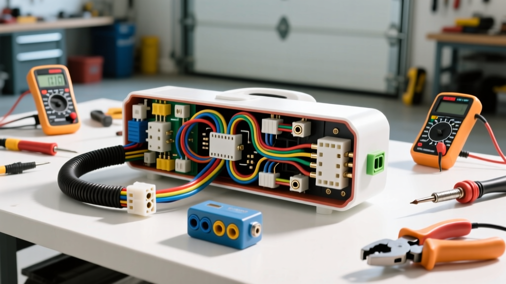
The Danger of Applying Residential Logic to Automotive DC Networks
When DIY enthusiasts transition from fixing residential 120V AC circuits to tackling automotive 12V DC networks, they often carry over the wrong assumptions. The mindset used for solving home repair electrical problems—such as using wire nuts, standard vinyl electrical tape, and low-impedance incandescent test lights—can lead to catastrophic failures in a vehicle. Modern vehicles utilize complex Controller Area Network (CAN) buses, pulse-width modulation (PWM) signals, and sensitive solid-state Body Control Modules (BCMs). Applying residential wiring techniques to these systems frequently results in shorted modules, electrical fires, and ghost faults.
This comprehensive cost and tool requirements analysis bridges the gap between residential DIY and professional automotive electrical troubleshooting. We will break down the exact financial investment required to build a proper automotive diagnostic toolkit, outline the specific wire gauge (AWG) and connector standards mandated by SAE J1128, and provide a real-world voltage-drop troubleshooting scenario.
Diagnostic Tool Cost Matrix: AC vs. Automotive DC
To accurately diagnose automotive electrical faults, you must abandon the hardware store electrical aisle and invest in high-impedance, automotive-specific diagnostic equipment. Below is a breakdown of the essential tools required, their estimated costs, and why residential equivalents fail.
| Tool Category | Automotive Requirement | Estimated Cost (USD) | Why Home Repair Equivalents Fail |
|---|---|---|---|
| Digital Multimeter (DMM) | 10 Megohm impedance, Auto-ranging, Min/Max, Duty Cycle | $80 - $350 | Standard $20 AC multimeters lack the sampling rate to read PWM signals and can load down delicate 5V sensor reference circuits. |
| Test Light / Logic Probe | High-impedance LED logic probe or Digital Storage Oscilloscope (DSO) | $25 - $250 | Incandescent test lights draw 2-4 amps. Probing an airbag squib circuit or CAN bus line with one can deploy the SRS or fry the ECM. |
| Wire Strippers & Crimpers | Precision ratcheting crimpers (e.g., for Deutsch or Weather-Pack pins) | $45 - $120 | Standard combination pliers crush terminal crimps, leading to high-resistance connections that melt under continuous 12V DC loads. |
| Parasitic Draw Tester | Low-amp clamp meter (0-10A DC range, 1mA resolution) | $60 - $180 | Standard clamp meters only read down to 0.1A (100mA), missing the 30-50mA sleep-mode parasitic drains common in modern vehicles. |
The Multimeter Impedance Factor
According to Fluke's automotive troubleshooting guidelines, a DMM used on vehicles must possess an input impedance of at least 10 Megohms. When measuring a 5-Volt Reference (5VREF) circuit—such as a Throttle Position Sensor (TPS) or Manifold Absolute Pressure (MAP) sensor—even a slight load from a low-impedance meter will pull the voltage down, causing the Powertrain Control Module (PCM) to log a false 'Circuit Low' diagnostic trouble code (DTC).
Wiring Consumables: SAE Standards and Repair Costs
Solving home repair electrical problems often involves twisting wires together and capping them with wire nuts or wrapping them in cheap vinyl tape. In the high-vibration, high-temperature, and chemically harsh environment of a vehicle engine bay, these methods guarantee failure. Automotive wiring requires specific insulation types and connection methods.
Wire Gauge (AWG) and Insulation Types
Automotive wire is not rated by the same standards as Romex house wire. You must use cross-linked polyethylene insulation (GXL or TXL) which resists heat, oil, and battery acid. Refer to Bosch Automotive Electrical Systems documentation for standard current capacities. Below is the standard AWG matrix for common 12V DC automotive circuits:
- 20 AWG (0.5mm²): CAN bus twisted pairs, low-current sensor grounds (Max 3-5 Amps).
- 18 AWG (0.8mm²): 5V reference circuits, fuel injector signal wires, ignition coil triggers (Max 7-9 Amps).
- 14 AWG (2.0mm²): Headlight feeds, horn circuits, power window motors (Max 15-18 Amps).
- 10 AWG (5.0mm²): Fuel pump power feeds, ABS module main power (Max 30-40 Amps).
- 4 AWG (20mm²): Starter motor solenoid feeds, high-output alternator B+ outputs (Max 100-120 Amps).
Connector and Splicing Consumables Budget
Building a proper consumables kit for automotive wiring repair will cost approximately $150 to $250 upfront, but prevents thousands of dollars in misdiagnosed module replacements.
- Adhesive-Lined Dual-Wall Heat Shrink (3M FP-301 or equivalent): $35/box. The inner layer of thermoplastic adhesive melts and seals out moisture, preventing capillary action from drawing water into the copper strands.
- Deutsch DT Series Connectors: $40/kit. Essential for under-hood sensor pigtails (e.g., oil pressure sensors, transmission solenoids) due to their silicone grommet seals.
- Tesa 51036 PET Cloth Wiring Tape: $15/roll. Standard vinyl tape unspells at 180°F (82°C) in an engine bay. PET cloth tape withstands 300°F (149°C) and provides abrasion resistance against firewall sheet metal.
- Ratcheting Terminal Crimpers (Open Barrel): $60. Required for modern Molex MX150 and TE Connectivity AMP connectors found in late-model ECM harnesses.
Advanced Troubleshooting: The Voltage Drop Parasitic Draw Test
One of the most common 'home repair' mistakes is pulling fuses one by one to find a parasitic battery drain, or breaking the negative battery cable to insert an ammeter. Both methods are flawed. Breaking the circuit wakes up modules, and pulling fuses drops network power, resetting the fault state. The professional method is Voltage Drop Testing across Fuses.
Step-by-Step Parasitic Draw Diagnosis
- Prepare the Vehicle: Close all doors, latch the hood (to activate the under-hood lamp switch), and lock the vehicle with the key fob outside the cabin to allow the BCM to enter sleep mode (usually takes 20-40 minutes).
- Configure the DMM: Set your high-impedance multimeter to the Millivolt (mV) DC scale.
- Test the Fuses: Place the red probe on one test point of a fuse in the underhood Bussed Electrical Center (BEC), and the black probe on the other test point. You are measuring the voltage drop across the fuse's internal element.
- Interpret the Data: Use the fuse voltage drop chart. For example, a standard 10A Mini (ATM) fuse has a resistance of roughly 7.5 milliohms. If a module is drawing 150mA (0.150A) while asleep, Ohm's Law (V = I x R) dictates a voltage drop of 1.12mV. If you read 1.1mV or higher on the BCM or Radio fuse, you have found your parasitic drain circuit without ever breaking the connection.
OBD2 Port and CAN Bus Pinout Reference
When diagnosing network communication faults (U-codes), understanding the Data Link Connector (DLC) pinout is mandatory. Never back-probe these pins with standard test probes, as spreading the terminal tension will cause intermittent CAN faults. Use dedicated DLC pin adapters.
- Pin 4: Chassis Ground
- Pin 5: Signal Ground
- Pin 6: CAN-High (Typically 2.5V to 3.5V active, Yellow or White wire)
- Pin 14: CAN-Low (Typically 1.5V to 2.5V active, Green or Black wire)
- Pin 16: Battery Positive (Unswitched 12V)
If you measure 120 Ohms of resistance between Pin 6 and Pin 14 (with the battery disconnected), the CAN bus termination resistors are intact. If you read 60 Ohms or infinite resistance, you have a shorted or open termination resistor, usually located inside the ECM or the instrument cluster.
Conclusion: Investing in Proper Diagnostics
Attempting to solve automotive faults using the same mentality and tools applied to home repair electrical problems is a fast track to damaged modules and stranded vehicles. By investing $300 to $500 into high-impedance diagnostic tools, proper ratcheting crimpers, and SAE-compliant GXL wiring materials, DIYers can safely and accurately troubleshoot everything from a parasitic draw to a corrupted CAN bus network. Respect the 12V DC environment, rely on voltage drop testing over resistance testing, and always adhere to manufacturer-specific wiring schematics.